Series and parallel circuits. Parallel speaker wiring combines all speakers positive speaker leads together and all negative speaker leads together.

How To Car Stereo Series Vs Parallel Wiring
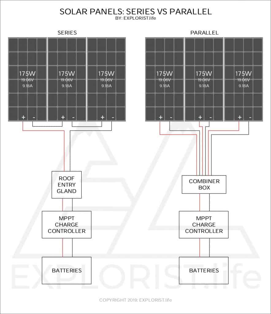
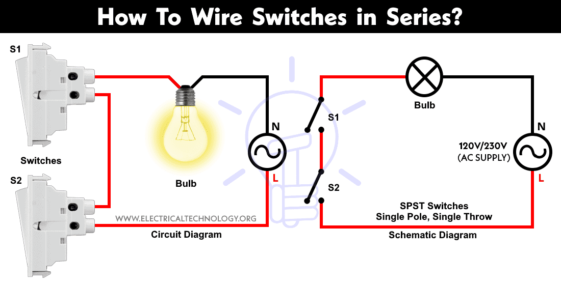
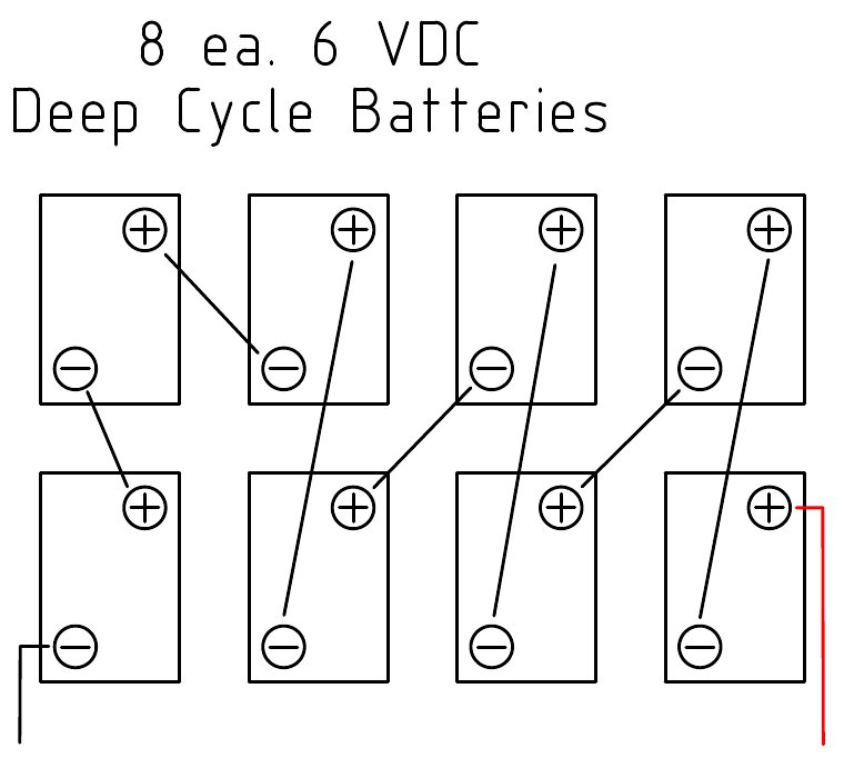
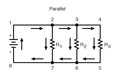
Series parallel wiring diagram. The two simplest of these are called series and parallel and occur frequently. First an example of a series circuit. With parallel wiring both pickups are wired directly to the output jack in the same way. Parallel circuits are the simplest electrical circuit to wire. Here we have three resistors labeled r 1 r 2 and r 3 connected in a long chain from one terminal of the battery to the other. Hopefully those looking for practical information on electrical circuits and wiring led components found this guide first.
Its likely though youve already read the wikipedia page about series and parallel circuits here maybe a few other google search results on the subject and are still unclear or wanting more specific information as it pertains to leds. Fig 3 fig 3. There are two basic ways in which to connect more than two circuit components. Wiring lights in parallel connection diagram. Components of an electrical circuit or electronic circuit can be connected in series parallel or series parallel. It should be.
The formular for series wiring is. Adding speakers in parallel decreases the overall resistance of the circuit. Parallel wiring refers to the way the coils are wired to the output jack. Components connected in series are connected along a single conductive path so the same current flows through all of the components but voltage is dropped lost across each of the resistances. This wiring doubles the voltage output resulting in a stronger and warmer tone. The wiring of lights in parallel connection is too simple and easy you need to connect to supply to each light bulb from the power source or we can said that the electric supply will connect to lights in parallel as i shown the below diagram.
Most humbucker pickups are wired using series wiring. How to wire lights in series.
Gallery of Series Parallel Wiring Diagram