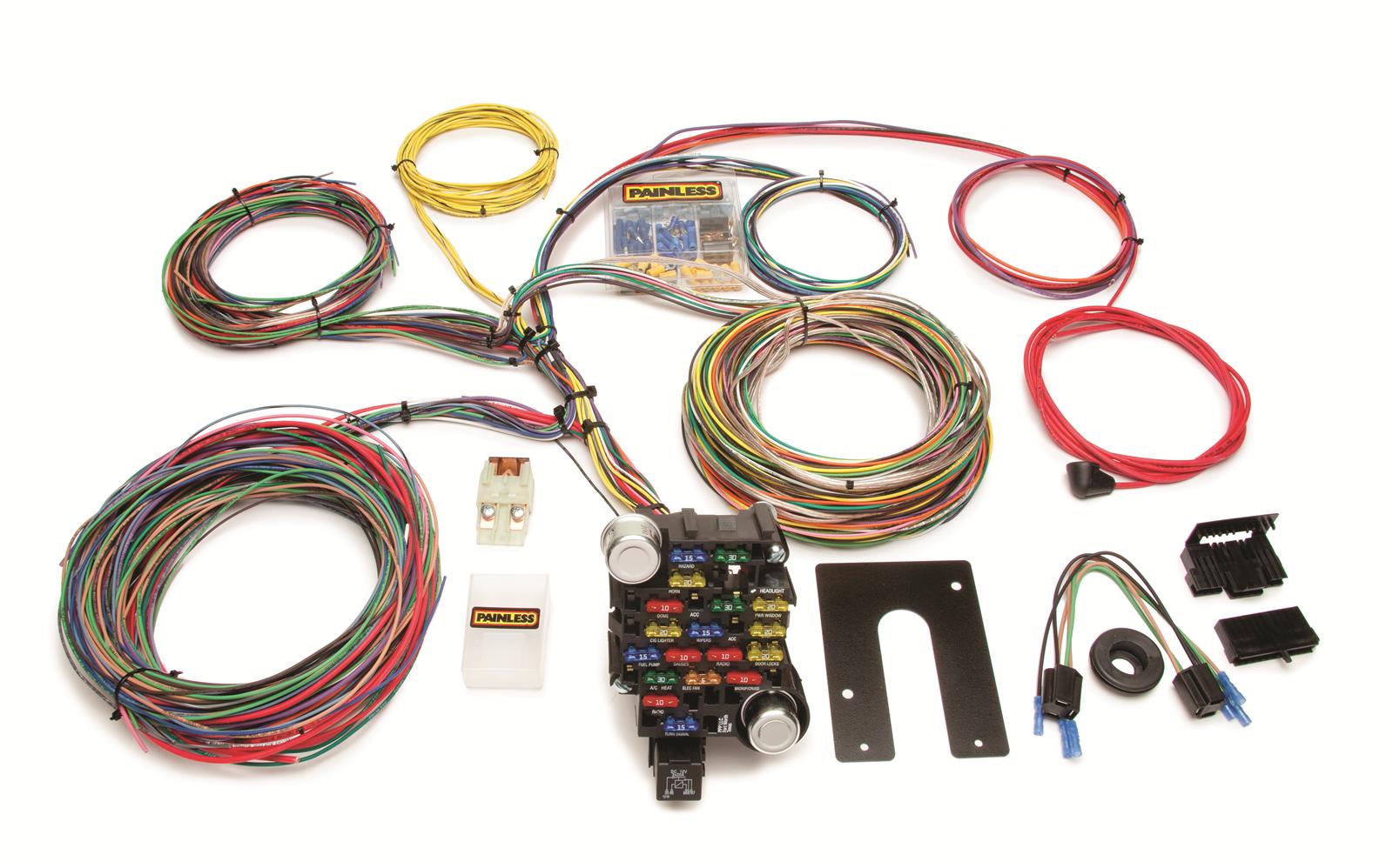
Route the wires to their proper location and terminate using terminals provided using the following chart. Painless performance will repair or replace defective products without.
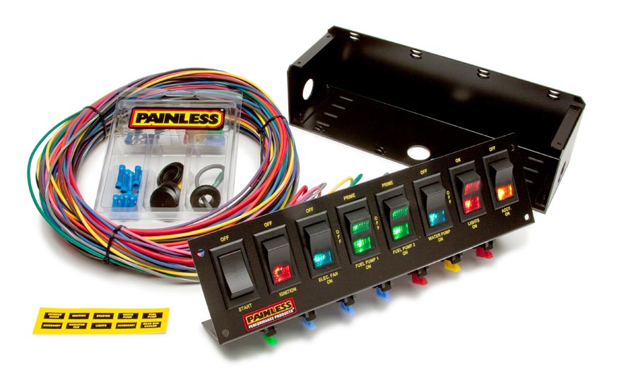
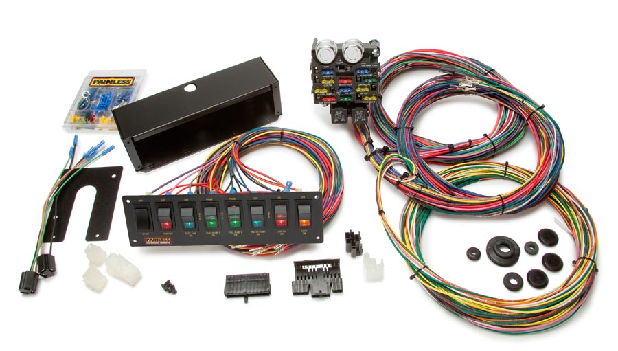
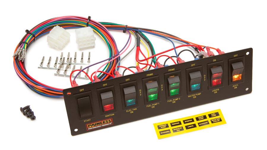
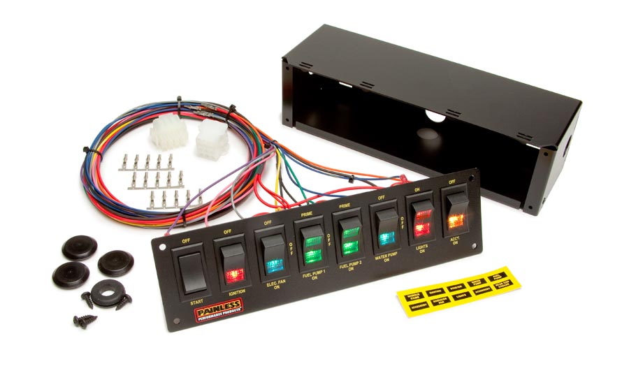
8 Switch Panel Fused W All Necessary Wiring Amp Hardware
Painless 8 switch panel wiring diagram. 6 switch 8 switch panels only. The following index is a list of what each color wire is used for. If anything is missing contact the dealer where you obtained the kit or. This wire helps protect the overall system and is very important. The contents of these instructions are divided into major sections as follows. Unroll the wire harness and route all the wires out the desired.
This will be your common ground point. A wiring diagram is a simplified traditional pictorial depiction of an electric circuit. 5020150202 8 circuit switch panel. Collection of painless wiring switch panel diagram. Painless performance wire harness kits include no ground wire except the black wire from the switch panel. It reveals the components of the circuit as simplified forms and the power and also signal links in between the devices.
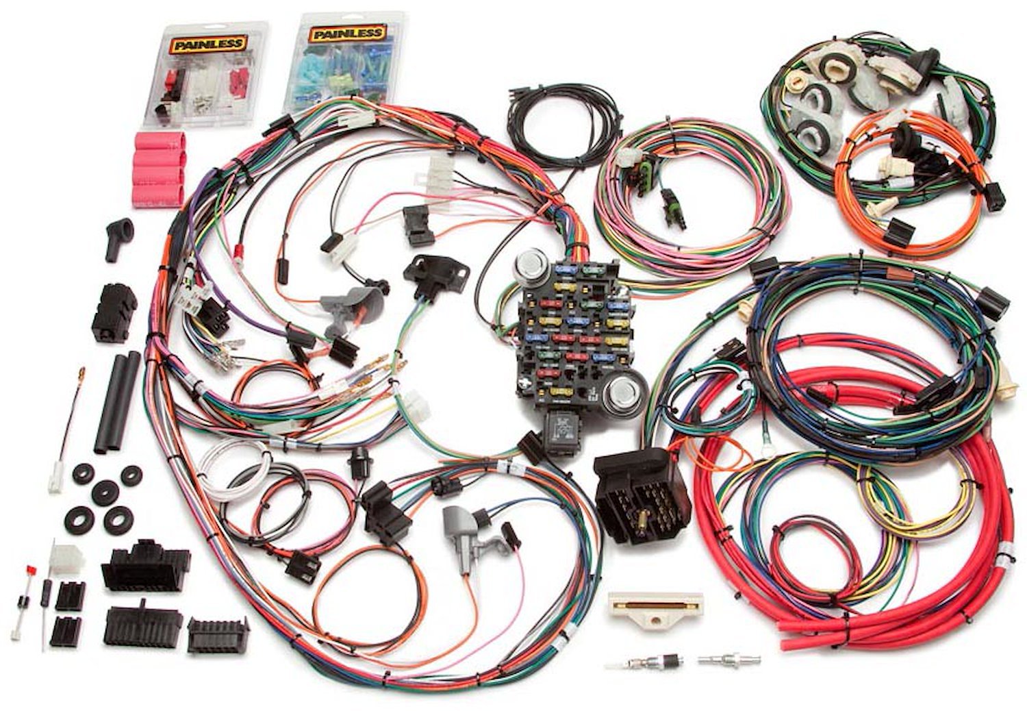
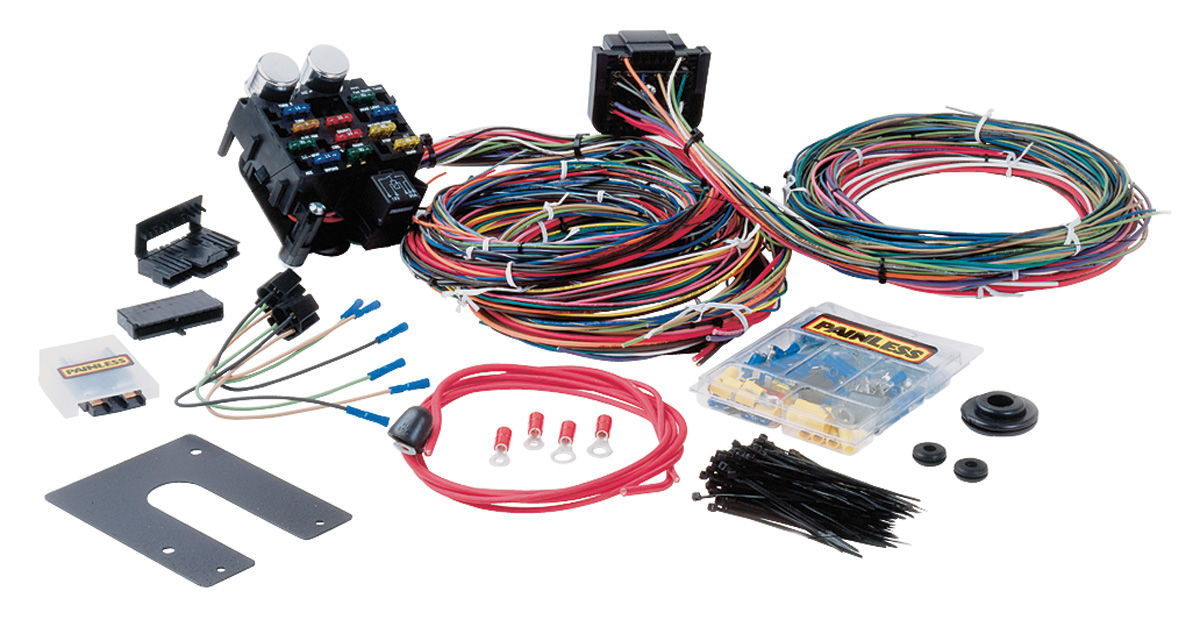
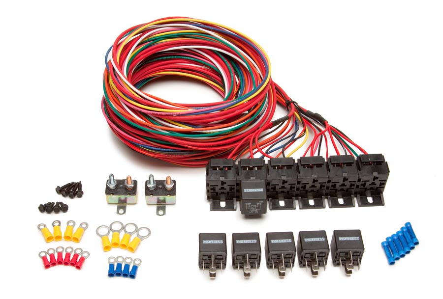
6 switch 8 switch panels only. 10 introduction 20 about these instructions 30 tools needed 40 pre installation and harness routing guidelines 50 general installation instructions 60 50001 8 circuit racing wire harness kit 70 5020150202 8 circuit switch. 30 contents of the painless wire harness kit refer to figure 3 1 to take inventorysee that you have everything youre supposed to have in this kit. 8 switch panel only. You must install fuse holder and 60amp fuse provided between end of red wire and battery source. Painless performance suggests a 1gauge ground cable from the negative battery terminal to the automobile chassis frame.
Rocker switch panels only. You must supply ground wire 14 16 gauge for all other circuits. 8 switch panel only.
Gallery of Painless 8 Switch Panel Wiring Diagram