These alarms meet approvals worldwide. Series 65 the series 65 range of conventional detectors incorporates well proven sensing technologies together with advances in materials and electronics technology.

Apollo Series 65 12v Relay Base 45681 508 Apollo S65 16 50 Vat Intruder Alarm
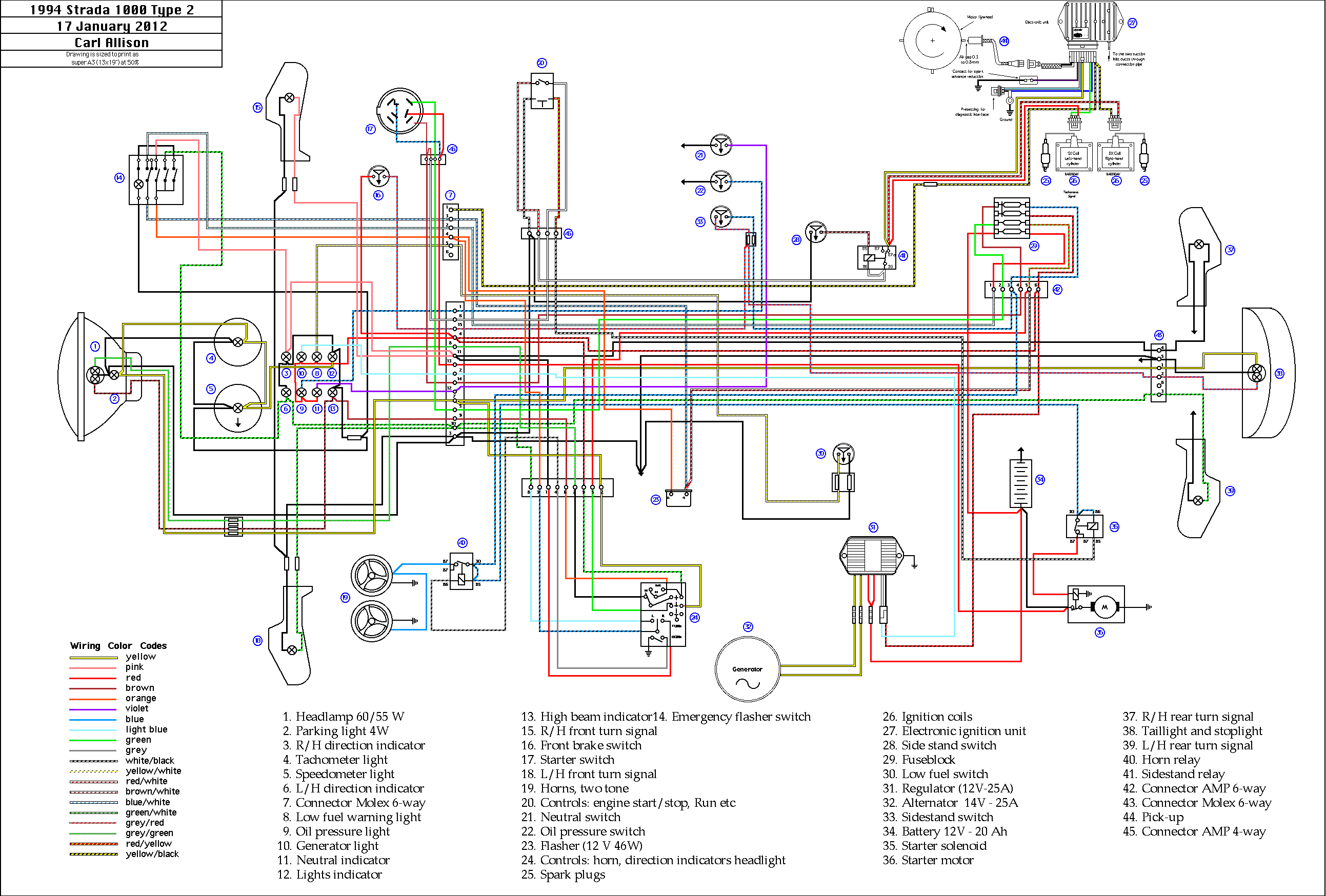
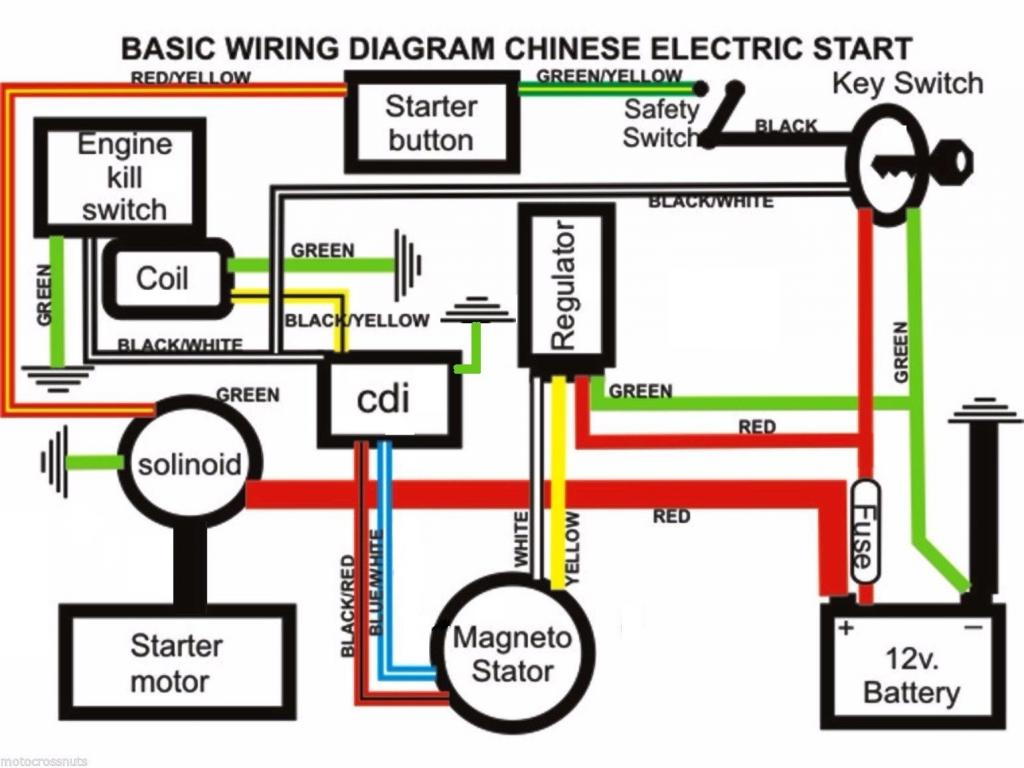
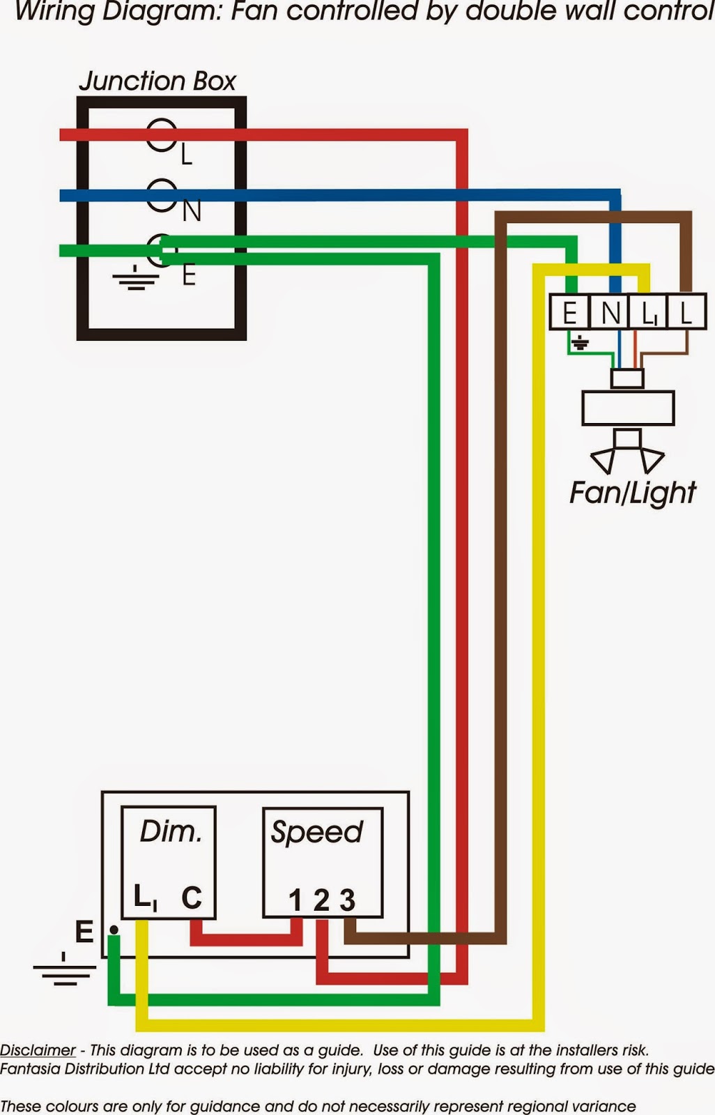
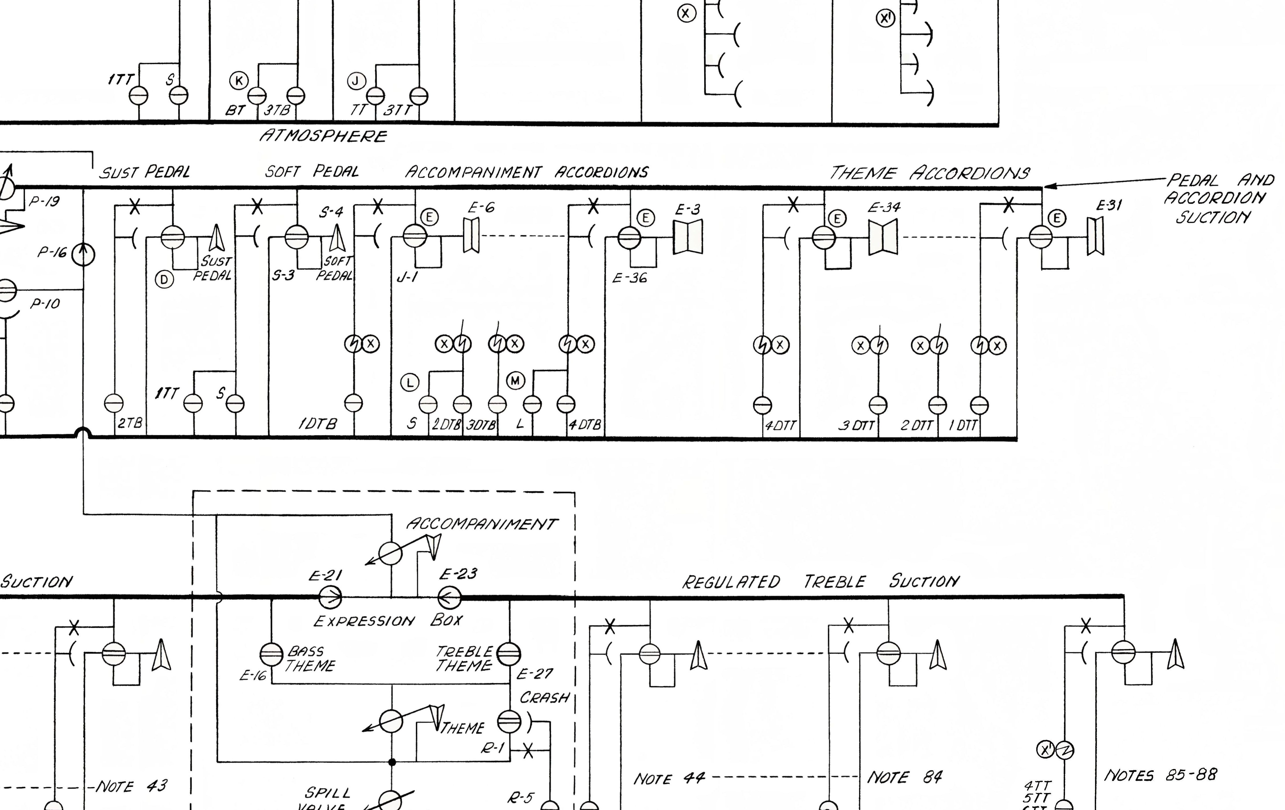
Apollo series 65 wiring diagram. This base can only be used with compatible control equipment. The series 65 range has a wide operating voltage of 933v and consists of ionisation integrating ionisation and optical smoke detectors four grades of heat detector and a range of bases. Truly we also have been noticed that apollo smoke detector wiring diagram is being just about the most popular topic at this time. Apollo 65 wiring diagram wiring diagram is a simplified satisfactory pictorial representation of an electrical circuit. Series 65 detectors are used on small to medium sized systems such as small industrial units shop units and guest houses. Apollo smoke detector wiring diagram apollo 65 series wiring for apollo smoke detector wiring diagram image size 583 x 337 px.
Series 65 smoke detector wiring diagram apollo series 65 smoke within apollo smoke detectors series 65 wiring diagram image size 583 x 337 px and to view image details please click the image. Apollo smoke detectors series 65 wiring diagram wiring diagram is a simplified up to standard pictorial representation of an electrical circuit. The base is fitted with a schottky diode on the l1 in and l1 out wiring terminals. Apollo smoke detectors series 65 wiring diagram. It shows the components of the circuit as simplified shapes and the skill and signal connections amid the devices. It shows the components of the circuit as simplified shapes and the power and signal links amid the devices.
45681 200 4 mounting base 45681 220 6 mounting base 45681 232 low profi. Here is a picture gallery about apollo smoke detectors series 65 wiring diagram complete with the description of the image please find the image you need. Series 65 incorporates well proven sensing technologies including an integrated circuit based on that used in xp95 analogue addressable detectors. Apollo 65 wiring diagram with apollo 65 wiring diagram image size 510 x 510 px and to view image details please click the image. Page 2 11ºc below rating 70ºc 60ºc fig 2 wiring diagram of series 65a zone with common remote indicator control panel refer to wwwapollo fi recouk for compatible panels the above instructions cover the following base model. The series 65 diode base is designed for use with conventional systems that have manual call points and detector bases on the same circuit.
The series 65 range has a wide operating voltage of 933v and consists of ionisation integrating ionisation and optical smoke detectors four grades of heat detector and a range of bases. Here is a picture gallery about apollo 65 wiring diagram complete with the description of the image please find the image you need. Series 65 incorporates well proven sensing technologies including an integrated circuit based on that used in xp95 analogue addressable detectors.
.jpg?mode=max&h=340)

