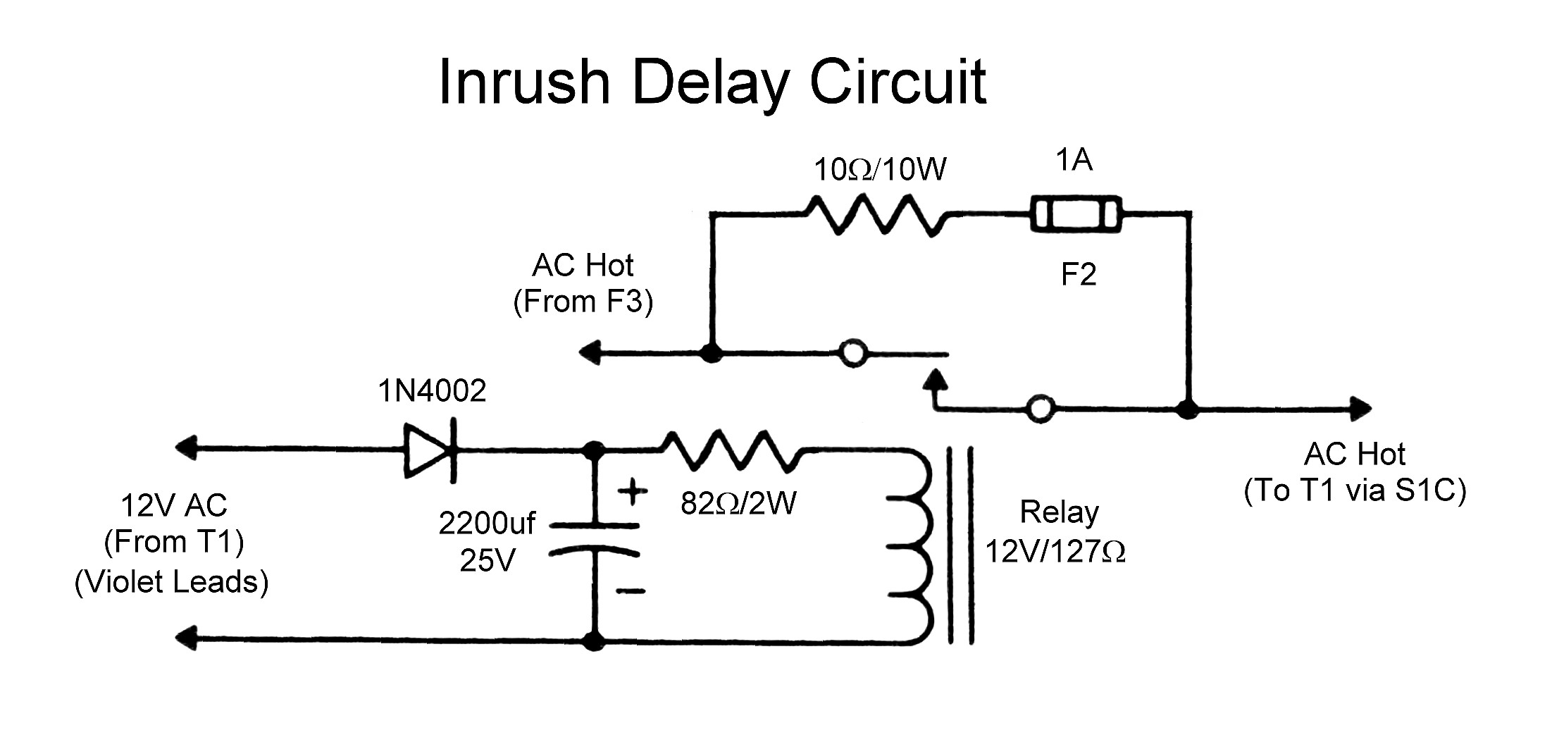
Check wiring for signs of damage from heat or overloads. To relay r h2 x2 h1 x1 neutral from generator or transformer.
9d9692 Neutral Ground Resistor Wiring Diagram Wiring Library
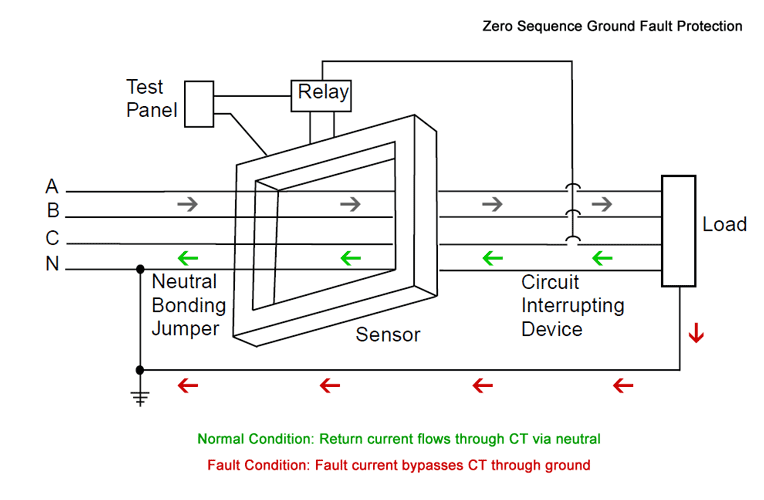
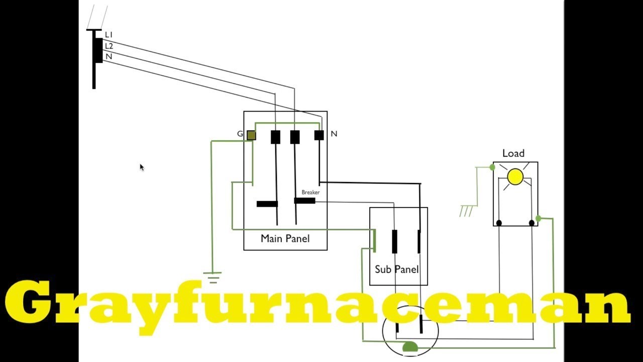
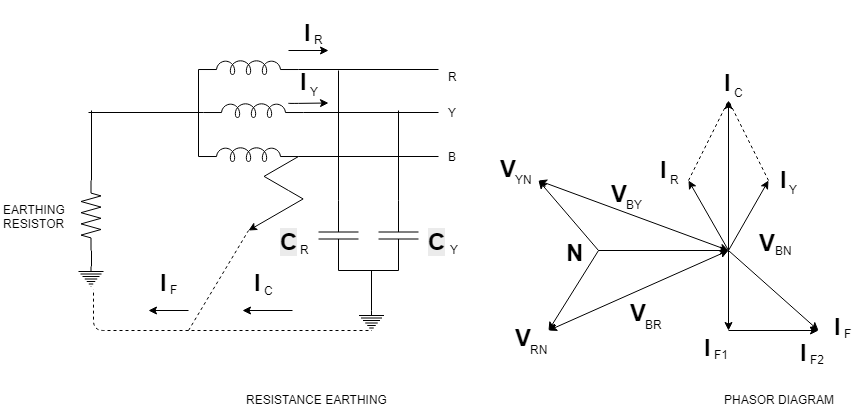
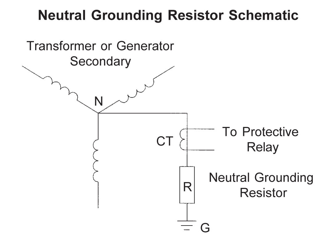
Neutral grounding resistor wiring diagram. Transformer secondary line to neutral voltage equals system voltage divided by 1732 neutral line to neutral voltage system voltage neutral grounding resistor figure 5. Neutral grounding resistors ngrs limit the fault current when one phase of the system shorts or arcs to ground. What is a neutral earthing resistor. Connect incoming cable to the entrance bushing cable. Check all internal connections for tightness. Wiring diagram of neutral grounding resistor ground fault relay voltagecurrent set currenttime increment decrement power on ngr fault ground fault sensor fault set mode test reset fail safe relay for neutral resistormonitoring ground fault relay pri earth s1 s2 n s2 earth resistor value 33kv 381 ohms 100kw.
A widely utilised approach to managing fault currents is the installation of neutral earthing resistors ners. Ners sometimes called neutral grounding resistors are used in an ac distribution networks to limit transient overvoltages that flow through the neutral point of a transformer or generator to a safe. Secure the neutral grounding resistor onto its base. In both types of grounding the resistor is connected between the neutral of the transformer secondary and the earth ground as shown in figure 5. Versionng111 19 download4931 stock total files1 file size37494 kb create datejune 15 2015 last updatedfebruary 17 2020 download fileneutral grounding resistors installation and maintenance instructions download. Make sure all connections are tight.
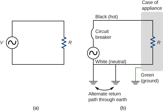
Install the cable entrance bushing in the hole provided and tighten securely if applicable. The neutral ground resistor will be rated for both current in amps and time in seconds. Between the neutral and the ground side of the resistor should be within 10 of the nameplate value. In the event that a ground fault condition exists the ngr typically limits the current to 200 400a though most resistor manufacturers label any resistor that limits the current to 25a or greater as low resistance. Another minor issue with some of our wiring diagrams is that in some cases where a white wire is used as a hot conductor either in switch leg situations or as a traveller in a 3 way or 4 way switch network the white conductor is not shown with means to identify it as a hot conductor and not a neutral. If the resistance of the element is more than 15 off from the nameplate value the resistors should be replaced.
Connect the resistor bus bar to the bushing if applicable. Ieee standard 32 1972 specifies the proper design criteria for 10 second extended time and continuous rated neutral grounding resistors.
Gallery of Neutral Grounding Resistor Wiring Diagram