View and download allen bradley 1734 vhsc5 installation instructions manual online. Module 1 houses the vhsc functionality.

1734 In017 En P Expansion Power Supply Power Supply
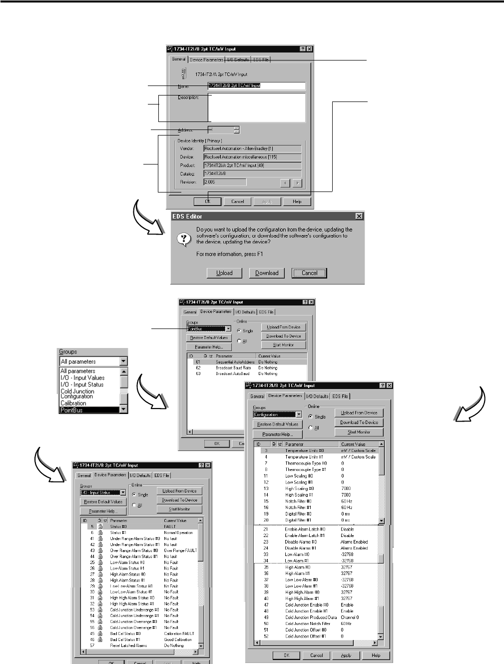
1734 vhsc24 wiring diagram. 1734 vhsc5 control unit pdf manual download. The module returns the count or frequency in the form of a 24 bit binary number 0 16777215 expressed in a 32 bit long word. Module 2 provides screw terminals necessary to access chassis ground chas gnd and common c. Wiring diagram module locking mechanism io module wiring base rtb rtb removal handle din rail locking screw orange 2 point io. 1734 vhsc24 1734 in003 analog input modules installation instructions 1734 ie2c 17340ie2v. Point io 5v dc and 24v dc very high speed counter module.
Because of the. 1734 tb 1734 tbs 1734 in511 wiring base assembly installation instructions 1734 tb3 1734 tb3s. Catalog numbers 1734 vhsc5 1734 vhsc24 1734 vhsc24k series c. Publication inb en p august wiring diagrams specifications general specifications these specifications are shared by all components of the point io system. 1734 vhsc24 1734 vhsc5 0 4 2 6 1 5 3 7 0 4 2 6 1 5 3 7 specification. The examples and diagrams in this manual are included solely for illustrative purposes.
Tb tbs tb3 and tb3s specifications out 0 out 1 out 1 out 0 cc v v load load v 1224v dc c common field power is supplied from power bus ob2ea b ib8s 8 channel safety sinking. Ladder the window comparisons part grt and les and other part of the process. 1734 tb 1734 tbs 1734 in511 wiring base assembly installation instructions 1734 tb3 1734 tb3s. The examples and diagrams in this manual are included solely for illustrative. The examples and diagrams in this manual are included solely for illustrative. Wiring diagram vhsc24 we turn on encoder a at input 0 and encoder aret at input 1 in logic structured text using the pmul instruction to convert encoder pulse data to mm scale.
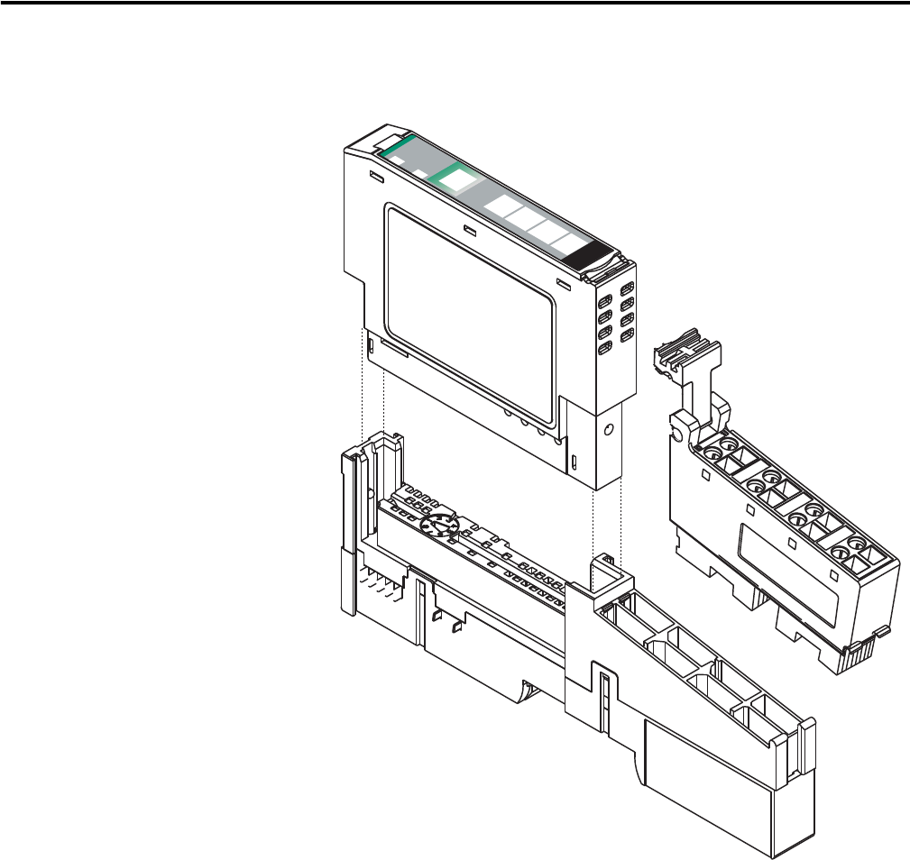
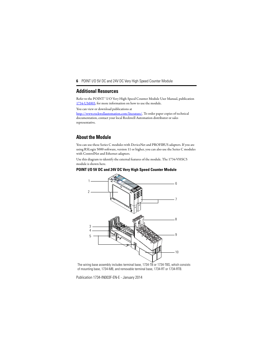
Vhsc5 or 15 24v dc vhsc24. Use this diagram to identify the external features of the module. Point io 5v and 24v encodercounter modules the wiring base assembly includes a terminal base 1734 tb or 1734 tbs which consists of a mounting base 1734 mb and removable terminal block 1734 rt or 1734 rts. Module 2 connects screws 4 and 5 and screws 6 and 7 for ease of wiring power to the input device. 1734 vhsc24 series c point io 24v dc very high speed counter module the vhsc is a two module set. Point io wiring diagrams 1734 ob2e 1734 ob4e 1734 ie2c in 0 in 1 chass chass load load load load load load 42014 42017 42015 v 1224v dc c common v 1224v dc c common v 1224v dc c common chass gnd chassis ground field power is supplied from power bus field power is supplied from power bus this supply will be connected to the.
Industrial automation wiring and grounding guidelines publication 1770 41 for more installation requirements. 1734 vhsc24k 1734 vhsc24 c series.
Gallery of 1734 Vhsc24 Wiring Diagram