On the other hand this diagram is a simplified version of this arrangement. This makes the procedure for assembling circuit simpler.

Bosch Maf Sensor Wiring Diagram General Wiring Diagram
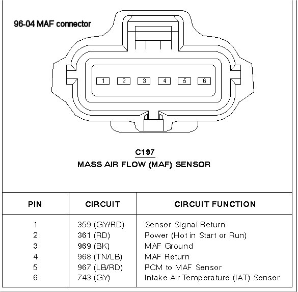
Mass air flow sensor wiring diagram. Mass air flow sensor wiring diagram thanks for visiting my internet site this post will certainly go over regarding mass air flow sensor wiring diagram. Mass air flow sensor electrical connections theory and troubleshooting from wiring diagram duration. 17 mafs ground black. Place your order online. We have gathered lots of pictures ideally this picture is useful for you and aid you in discovering the solution you are looking for. Automotive electronics from schematics by joseph 1231 views 842.
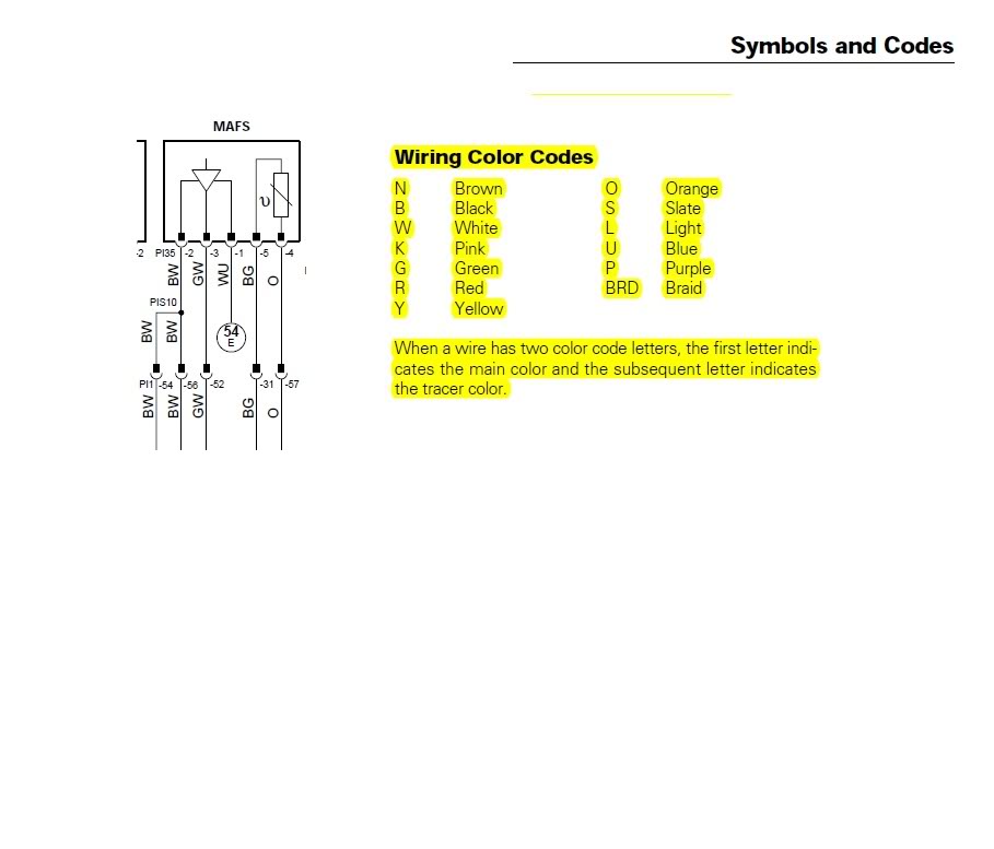
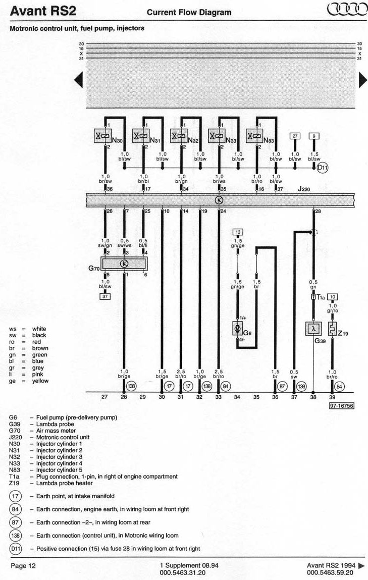
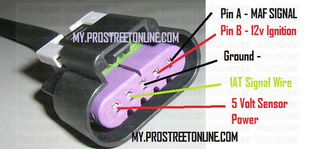
Wire b 12v power wire c ground wire d air flow signal out s14 sr wiring diagram and ecu pin out for a sr20det motor out of a nissan. 16 mafs signal input mass air flow sensor white. Boschmass air flow sensor. Wiring specialties mass air flow sensor mafs connector 300zx mass air flow sensor wiring diagram the diagram offers visual representation of an electrical arrangement. The following schematic shows a typical circuit diagram of the mass air flow maf sensor system. Coupled with a 5 speed 6 speed manual or a 6 speed automatic.
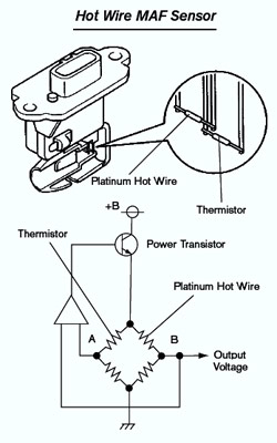
Nissan sentrapulsarnx repair guide the maf uses a heated wire or film which is stretched across the incoming air flow. Products 1 30 of from filters to ducts maf sensors to manifolds we have the air filter boxes components air filters components mass air flow maximum efficiency reduces engine weareasy installation. The primary components of the maf sensor are thermistor a platinum hot wire and an electronic control circuit. The mass air flow sensors converts the amount of air drawn into the engine into a voltage signal.
Gallery of Mass Air Flow Sensor Wiring Diagram