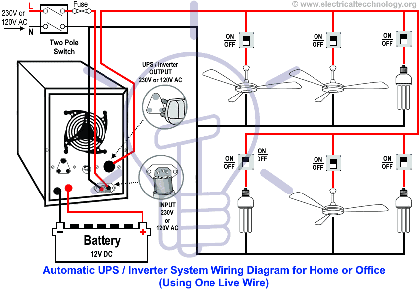
It shows how the electrical wires are interconnected and can also show where fixtures and components may be connected to the system. It does not show the actual locations of the components.

Float Switch Installation Wiring Amp Control Diagrams Apg
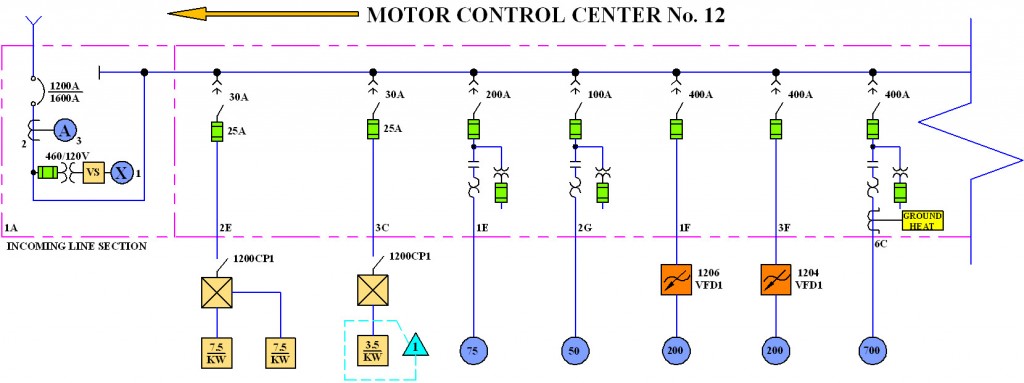
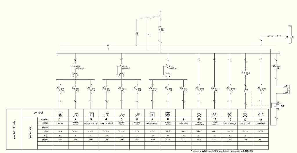
Line wiring diagram. A wiring diagram is a type of schematic that uses abstract pictorial symbols to show all the interconnections of components in a system. Red wire green wire. A ladder or line diagram is a diagram that shows the function of an electrical circuit using electrical symbols. Single line diagram sld we usually depict the electrical distribution system by a graphic representation called a single line diagram sld. Some wiring diagrams are so large and contain so many components that the diagram is broken up into numbered and lettered sections. A wiring diagram is a simple visual representation of the physical connections and physical layout of an electrical system or circuit.
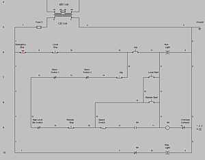
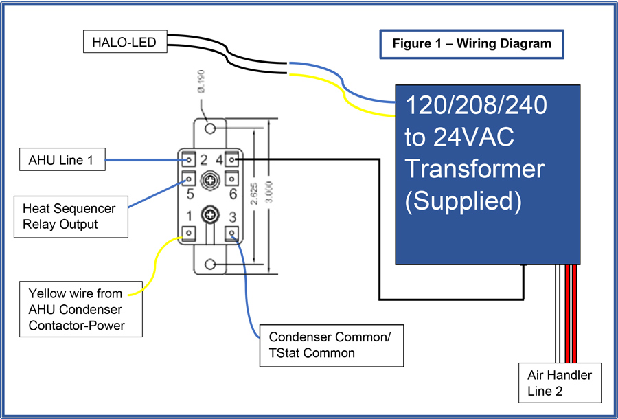
Ladder diagrams allow a person to understand and troubleshoot a circuit quickly. This wiring diagram shows the standard way to wire telephone jacks the single line set will use the following pairs depending on your cable. It is very versatile and comprehensive because it can depict very simple dc circuits or a very complicated three phase system. A wiring diagram is a detailed diagram of each circuit installation showing all of the wiring connectors terminal boards and electrical or electronic components of the circuit. Wiring diagrams are made up of two things. Usually drawn like a ladder hence the name ladder diagram.
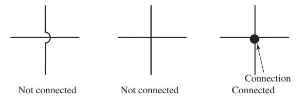
Symbols that represent the components in the circuit and lines that represent the connections between them. A single line can show all or part of a system.
Gallery of Line Wiring Diagram