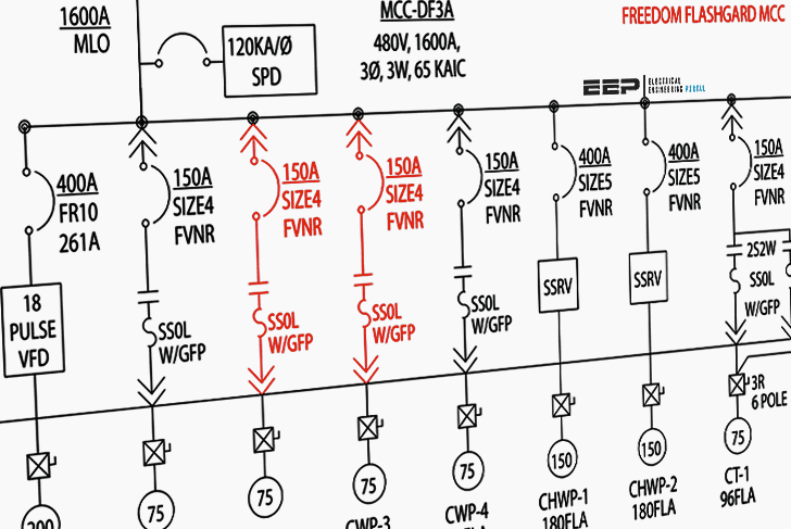
Basics 5 480 v mcc 1 line. Wiring diagrams function very much the same way but employ a different set of symbols.

Wiring Diagram Symbols In Addition Consumer Unit Wiring
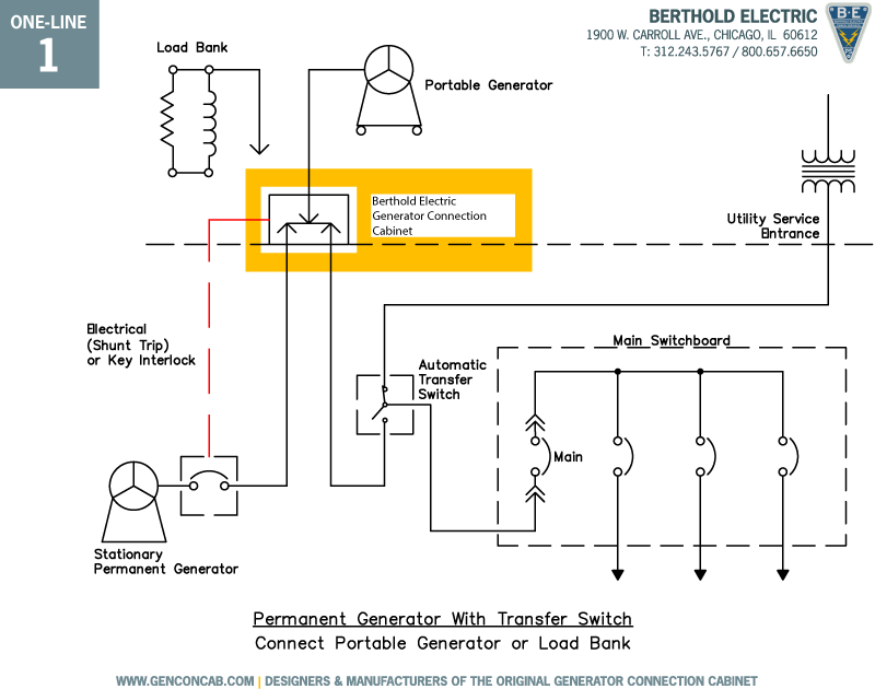
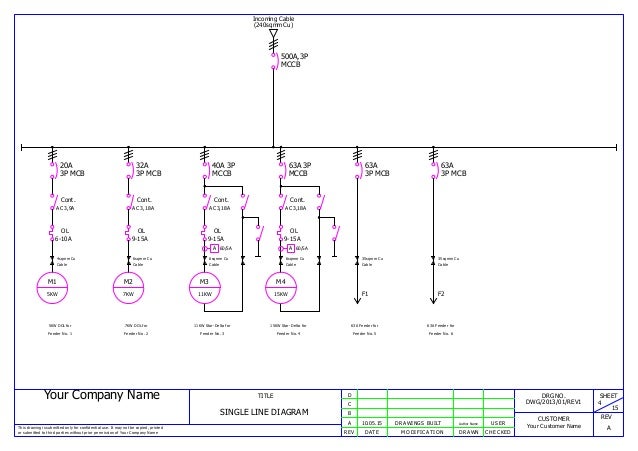
Single line wiring diagram. Basics 8 aov elementary block diagram. Basics 3 416 kv bus 1 line. Basics 9 416 kv pump schematic. It is very versatile and comprehensive because it can depict a very complicated three phase system. We use universally accepted electrical symbols to represent the different electrical components and their relationship within a circuit or system. In order to analyze a power system under load conditions or upon the occurrence of a fault it is essential to draw the per phase.
There mainly two types of wiring diagram are used one is single line diagram and another is multiline diagram. Phase 2 l1 l2 l3 ground when used. Single line diagram sld we usually depict the electrical distribution system by a graphic representation called a single line diagram sld. A single line can show all or part of a system. Click more in the symbol library drop down menu and there are even more electrical symbols to choose from. Circuit diagram or schematic diagram not classified into single line or multiline diagram.
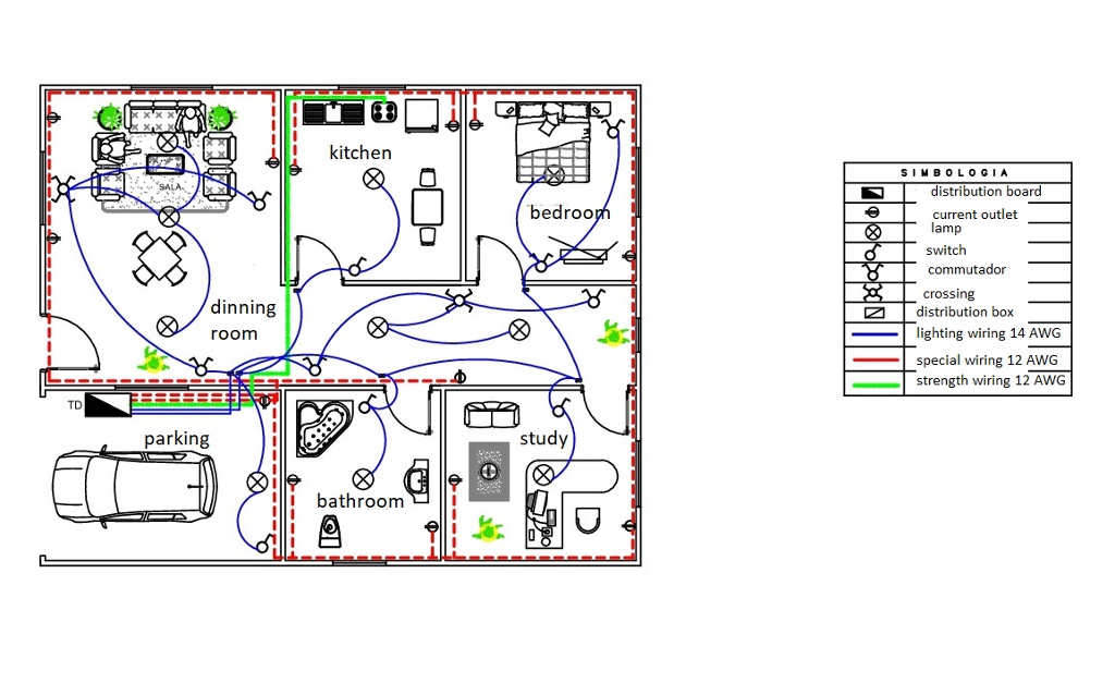
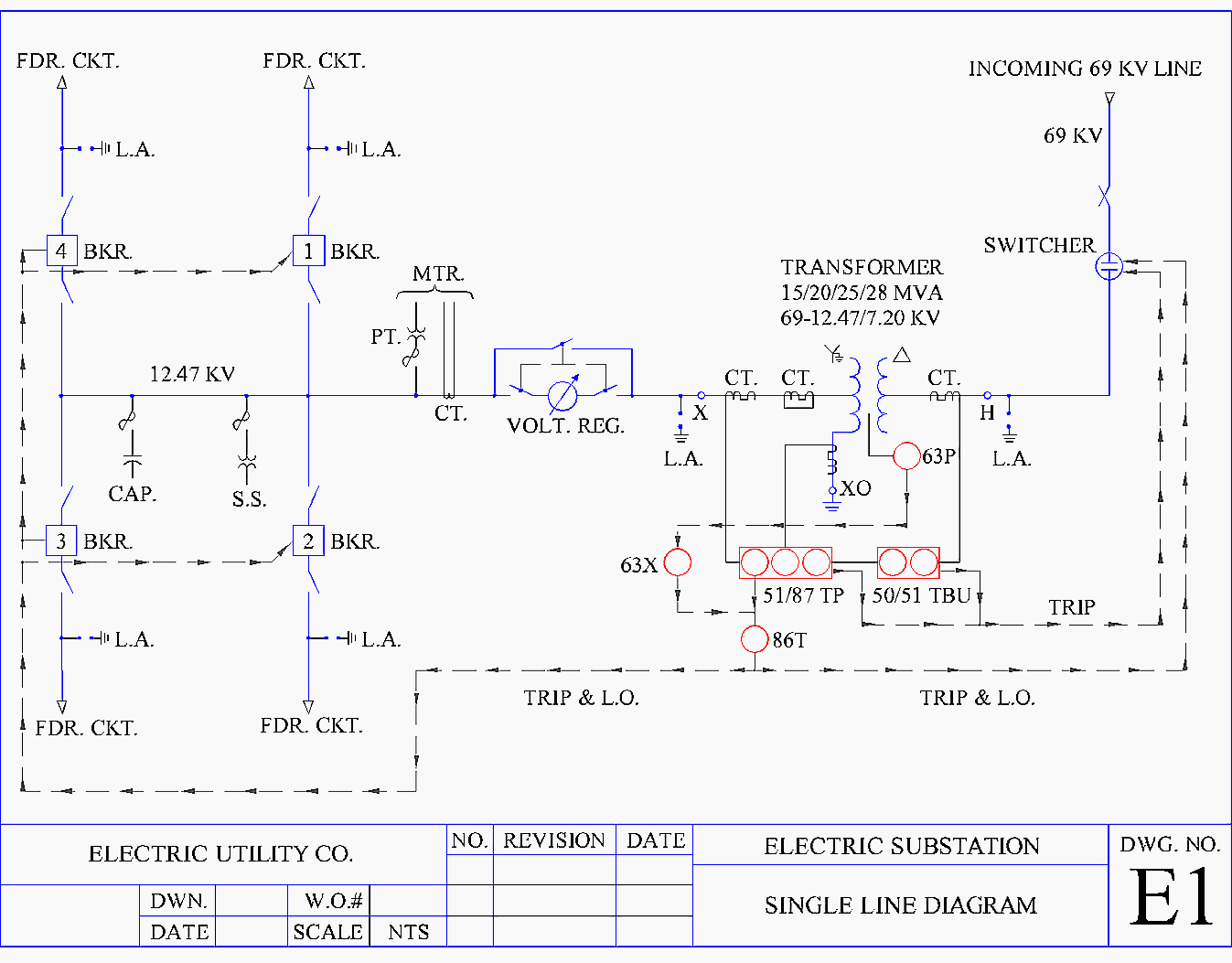
Typical controller markings typical elementary diagram iec typical controller markings typical elementary diagram table 4 control and power connections for across the line starters 600 v or less from nema standard ics 2 321a60 1 phase 2 phase 4 wire 3 phase line markings l1 l2 l1 l3. Basics 10 480 v pump schematic. Electrical elements such as circuit breakers transformers capacitors bus bars and conductors are shown by standardized schematic symbols. Single line diagrams show the overall conceptual layout of a circuit. One of the most important wiring diagrams is what we called architectural wiring diagram. Basics 7 416 kv 3 line diagram.
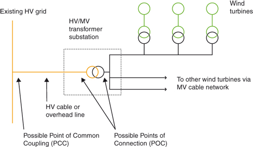
They typically condense three phase connections down to single lines for simplicity. Phase 1 l2 l4. Instead of representing each of three phases with a separate line or terminal only one conductor is represented. Impedance and reactance diagrams. A single line drawn on these diagram wills always indicate at least two conductors. Single line diagrams are where upper level details like generators main transformers and large motors are shown.
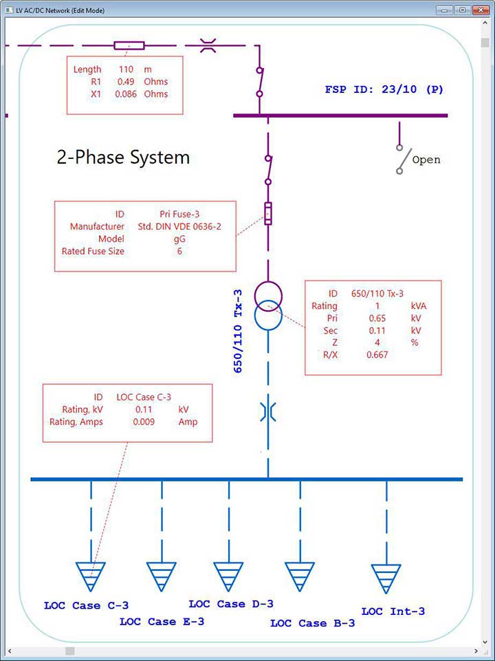
Block diagrams often used for higher level less detailed descriptions for understanding overall concepts use the same easy drawing tools and are easy. The one line diagram has its largest application in power flow studies. In power engineering a single line diagram also sometimes called one line diagram is a simplified notation for representing a three phase power system. This is because the diagram shows multi conductor cables with a single line. A single line can show all or part of a system. Three phases are denoted by a single conductor ie power system is assumed in a balanced steady state.
Wiring diagram is mainly used to know how connections are actually made. 4a architectural wiring diagram the architectural wiring diagram can be referred to as a one line diagram. Basics 11 mov schematic with block included basics 12 12 208 vac panel diagram. It is very versatile and comprehensive because it can depict very simple dc circuits or a very complicated three phase system. Basics 6 72 kv 3 line diagram. What is a single line diagram.
Basics 4 600 v 1 line. A single line diagram is method of simplified representation of a three phase power system. We usually depict the electrical distribution system by a graphic representation called a single line diagram sld. It is a form of b.
Gallery of Single Line Wiring Diagram