Limitorque mx electronic actuator fcd lmenim2306 06 1013 2. Check all unit wiring to ensure that it coincides with the applicable wiring diagram.

Mx Series Action Automation Valve Automation Services
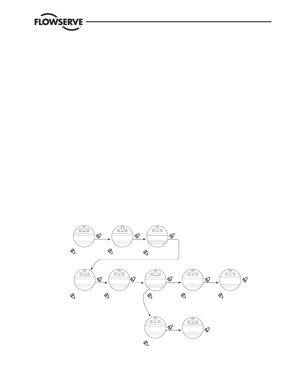
Limitorque mxa wiring diagram. Limitorque wiring diagrams are listed for most standard and optional electricalelectronic configurations of currently supported products. Carefully check for correct motor rotation direction. Mx and qx wiring diagrams 29 14. Standard wiring diagram 25 figure 315 removing outer plastic jacket 26 figure 316 separating cable parts 26. 1 important notes 7. When flowserve limitorques qxm or mxa actuators.
And monitoring document for wiring diagrams and modulating performance characteristics. E september 2002 limitorque. A wiring diagram is a simplified standard photographic representation of an electrical circuit. This information is located on the unit nameplate. Mx and lb2 testing and modulating performance while the qxm and lb1 will meet the majority of require. Flowserve limitorque is a global leader in quality manu facturing.
If the motor is driving the valve in the wrong direction interchange any two leads on three phase motors. Having supported the limitorque product for over 30 years we try to share our knowledge through this portal with our customers in a personalized experience. It reveals the parts of the circuit as simplified forms and the power and signal connections in between the tools. 339 network wiring profibus dppa installation 29 3310 network wiring devicenet 29. Limitorque pro offers video tutorials blog post and other resources in an effort to provide premium support to our loyal customers. Network protocol connections 34 141 network wiring ddc modbus 34 142 network wiring foundation fieldbus h1 36 143 network wiring profibus dp and pa 38 144 network wiring devicenet 41 145 network wiring hart 42.
122 wiring diagram configurator 28 13. The same unexcelled use of certified materials is found in the mx as in limitorques naval and nuclear quali fied electric actuators. L120 10 through 40 typical wiring diagram 5 2 5 3 figure 52 l120 10 through 40 drive sleeve housing cover parts breakdown 5 4 5 5. Limitorque l120 series installation maintenance for l120 10 through l120 40 limitorque actuation systems. Mxa wiring diagrams single phase. Variety of limitorque l120 wiring diagram.
All limitorque plants are certified to iso 9001 standards the recognized benchmark for quality all over the world.
Gallery of Limitorque Mxa Wiring Diagram