It shows the components of the circuit as simplified forms and also the power and signal links between the tools. Wiring diagram how to bypass ballast for led tube.
Led Fluorescent Retrofit Wiring Diagram Wiring Diagram
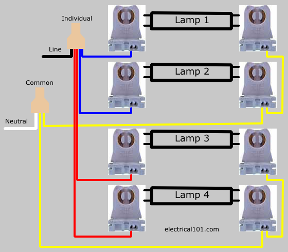
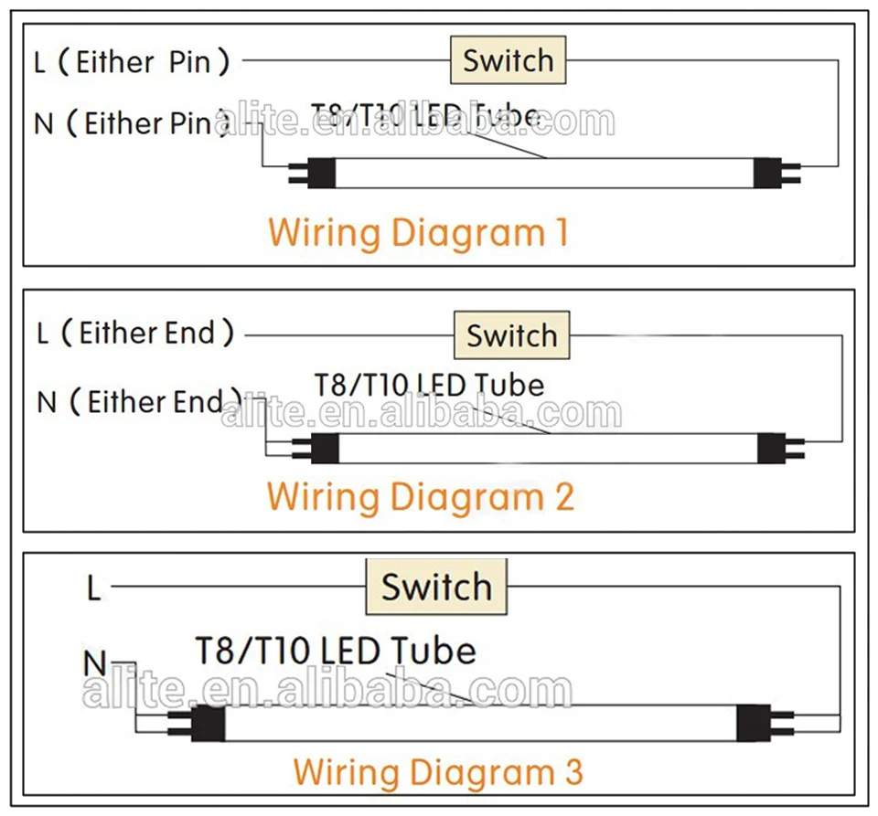
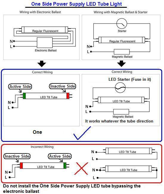
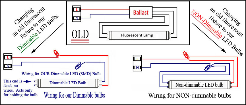
Led tube light wiring diagram. For 2 lamp rapid start fixture ballast wired in series when line and neutral wires are 12 or 14 awg size use tan or yellow wire connectors. Led tube lamp only requires power at one end. A wiring diagram is a simplified conventional photographic depiction of an electric circuit. Led direct wired dual ended wiring diagram. Then group one load wire from one side with one neutral wire from the other. Cut back additional wiring on opposite side of ballast as the led tube lamp only requires power at one end.
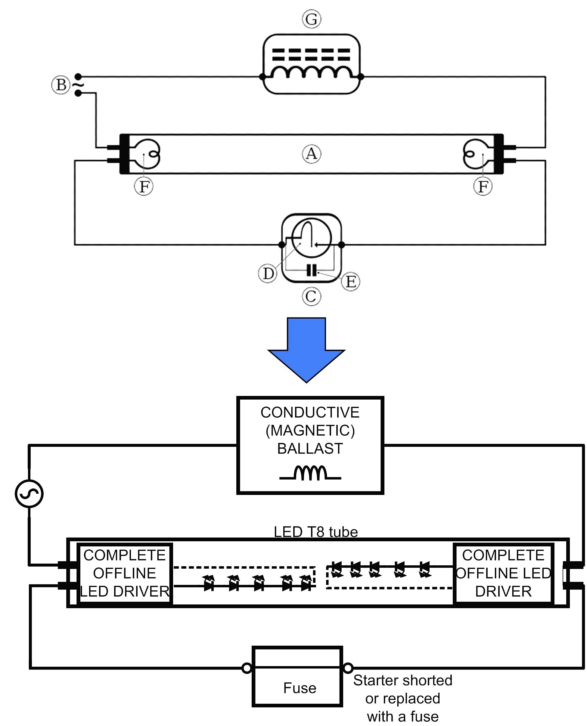
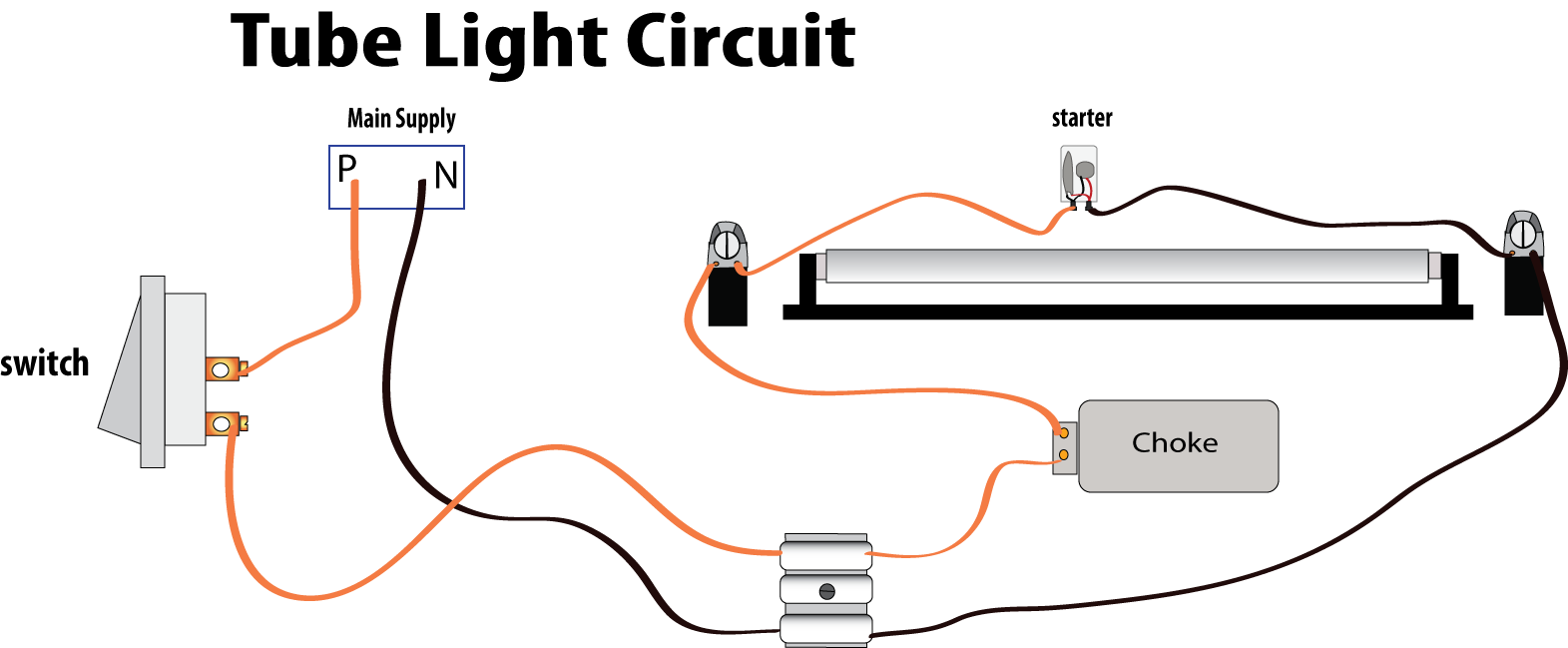
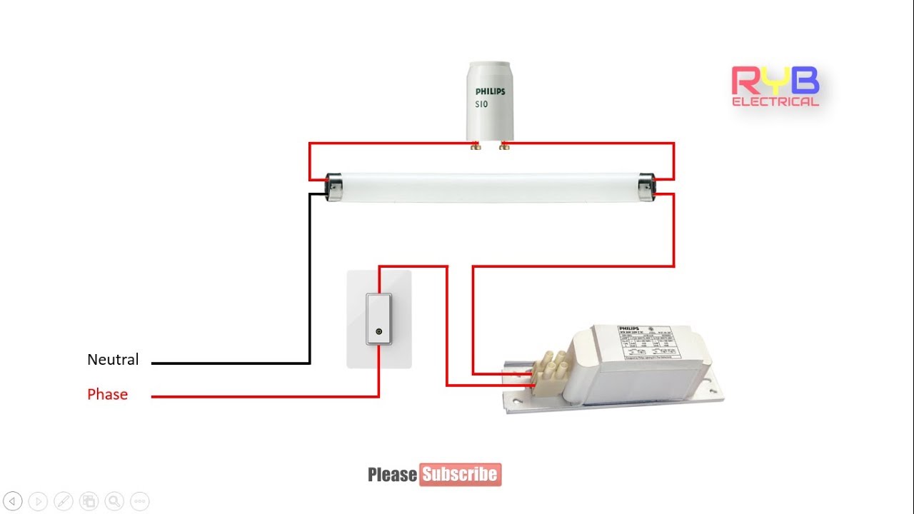
A glow starter or commonly known as starter is used in the tube light circuit to provide an initial current to filaments of the tube light. A wiring diagram is a simplified standard pictorial representation of an electrical circuit. Common wires yellow are connected to neutral. These connections can be reversed. Strip the load and neutral wires from the rst set of wires that were cut. October 31 2018 by larry a.
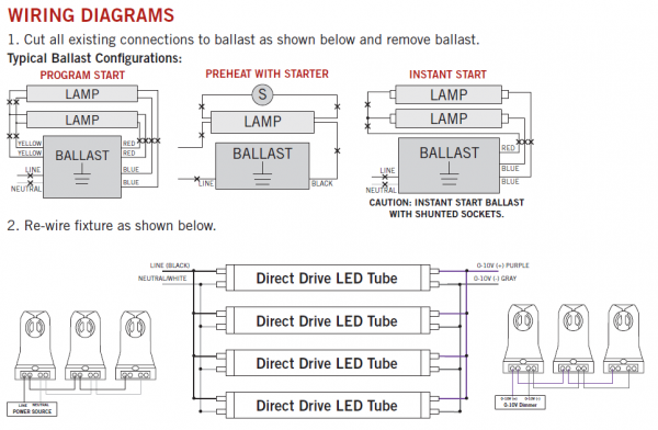
Remove the ballast from the tube lamp housing and save the original wiring that connected to the 110vac. Wellborn assortment of t8 led tube light wiring diagram. Remove the ballast from the. Its purpose is to show you step by step how to convert your current 4 foot t8 or t12 fluorescent tube light fixture to use the starled ballast. Assortment of led tube light wiring diagram. Individual lampholder wires blue and red are connected to line.
Use push in connectors or wire. How do lightbulbs work. It shows the parts of the circuit as streamlined forms and also the power and signal connections between the gadgets.
Gallery of Led Tube Light Wiring Diagram