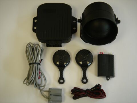
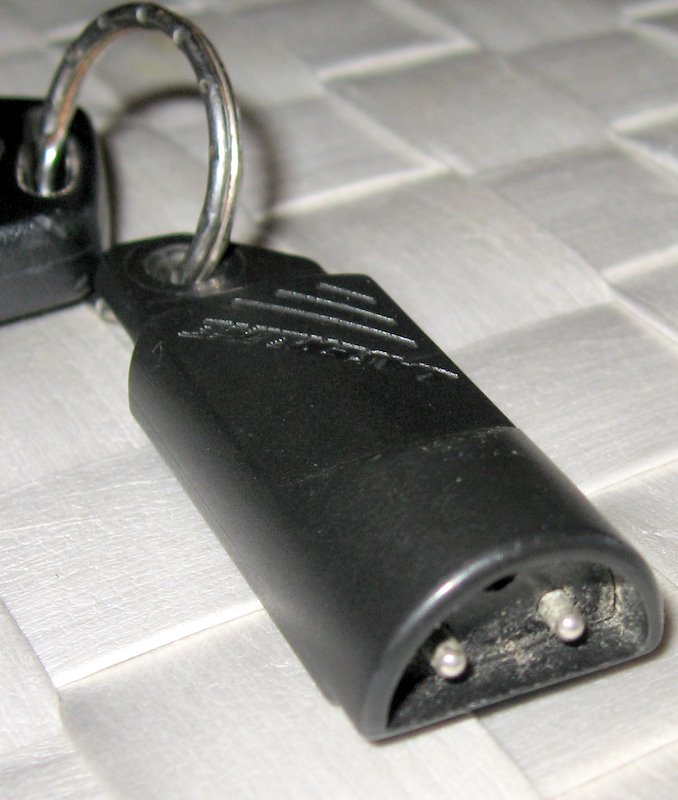
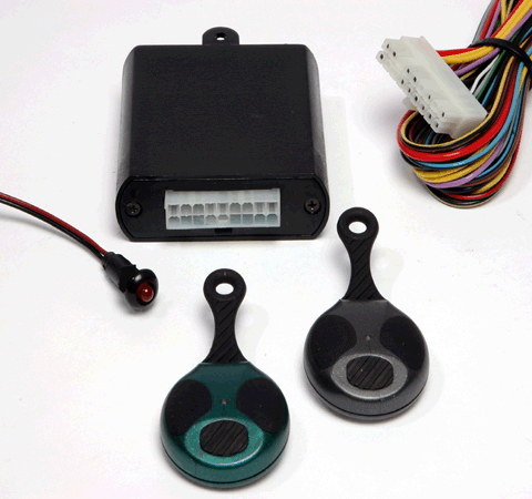
290i2 car alarm pdf manual download. Laserline model 921k immobiliser is a sophisticated electronic device for vehicle protection which ensures very reliable protection with a simple operation procedurethe system consists of a control unit ledreceptacle and two code keys.
Car Amp Van Security
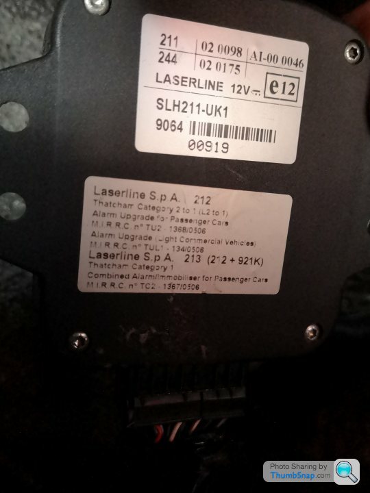
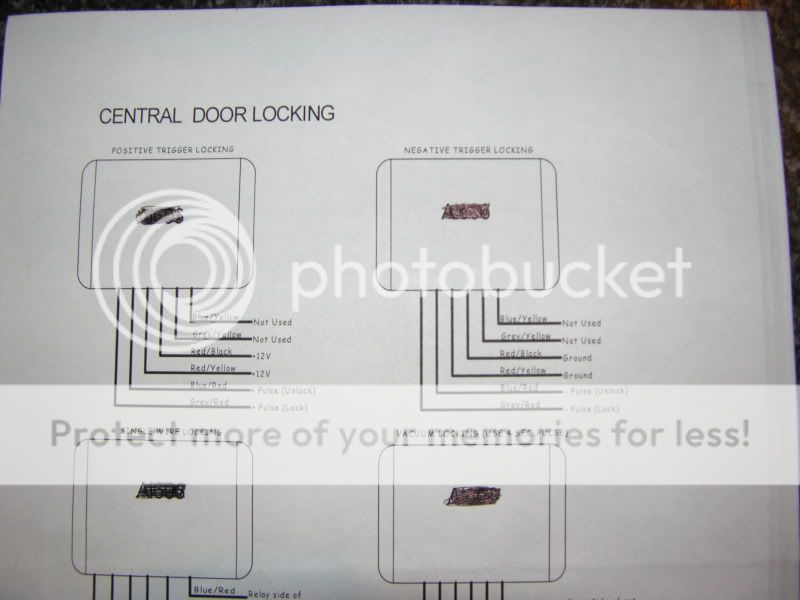
Laserline alarm wiring diagram. Laserline 213 thatcham category 1 alarm thatcham category one alarm immobiliser system digitek 7854t dg thatcham cat 1 bike alarm. At the end of the alarm cycle if the same sensor is still activated the alarm will trigger an alarm cycle again. Can bus and keyless alarm upgrades. Front and rear parking sensors. A smoke or heat detector can be installed to the existing or new home wiring. The modular system is normally used when there is limited space in the engine compart.
All information published in the vehicle diagram pages is gathered from sources which are thought to be reliable and accurate but we advise everyone check and verify our information by testing with a computer friendly test light to ensure proper connections are made. This is the basic fire alarm system used in household wiring. The 270 alarm sytem is a compact unit where the alarm and siren are combind the 278 alarm system is a modular unit where the alarm and siren are seperate. Alarm cycle limitation the system will automatically exclude the sensor which has generated 8 alarm cycles. View and download laserline 290i2 user manual online. Laserline car alarm wiring diagram 26102018 26102018 7 comments on laserline car alarm wiring diagram hi there save hours of searching online or wasting money on unnecessary repairs by talking to a 6ya expert who can help you resolve this.
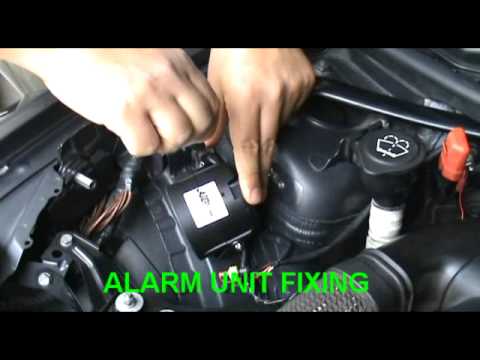
All the other sensors will continue to protect your car. Laserline automotive ltd is the new distributor of laserline and flashpoint car security and parking systems. Car alarms and immobiliser syatems. The maximum number of alarm cycle for every sensor is 8. The 921k immobiliser deactivates the main electric circuits. Alarm unit 908 siren 3 278 system components your alarm system consists of the following items.
In our basic wiring diagram a single or multiple heat and smoke detectors are installed in the home by connecting the live line or hot neutral ground and an interconnected wire to the alarm. Disarming the alarm system press button a armdisarm located on the right of the remote control see fig. 1the direction indicator lights will flash once and the alarm may give one audible tone programmable function generated at the same time to indicate that the alarm system has been disarmed. As a company we specialise in the following.
Gallery of Laserline Alarm Wiring Diagram


/dac3f1af-783d-40bf-a72f-317352421d46.jpg)

