The brake control must be installed with a 12 volt negative ground system. Installing a brake controller involves disconnecting the vehicle battery mounting the brake controller onto dash and plugging the unit in with a vehicle specific wiring harness.
Journey Trailer Brake Controller Wiring Diagram Journey
Journey brake controller wiring diagram. Dodge trailer brake controller wiring diagram 2014 dodge ram trailer brake controller wiring diagram dodge ram trailer brake controller wiring diagram dodge trailer brake controller wiring diagram folks understand that trailer is a car comprised of quite complicated mechanics. I have the following information on setting up the journey hd brake controller 52740. Elecbrakes is designed to operate 1 to 2 braked axles. There are several potential causes for this issue. Journey hd brake control light green wire fig. Prior to towing the output power must be adjusted for the individual trailer being towed.
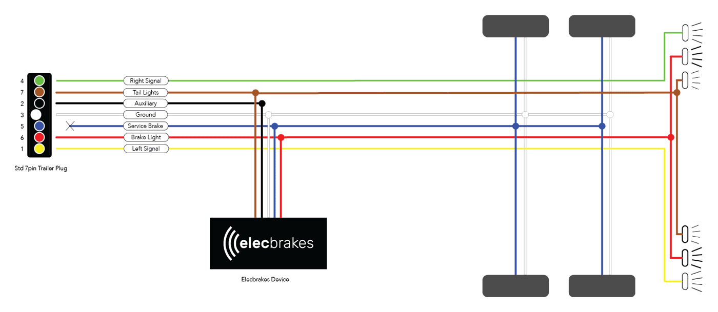
To install with a positive ground system use tekonsha pn 3191 2. Electric brake controller wiring diagram. Break away systems may be added to the service brake circuit. Auxiliary connection is optional it may be connected to any 12v to 24v constant power source or left unconnected. Fuse box diagram location and assignment of electrical fuses for dodge journey 2011 2012 2013 2014 2015 2016 2107 2018 2019. This automobile is designed not only to travel one place to another but also to take heavy loads.
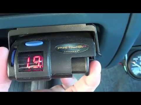
We will cover a few features of this brake controller for one it is a nice and small device. If your valley journey brake controller 52650 delivers a constant brake output signal to your trailer connector you can use a circuit tester such as 40376 to determine if the fault is in the controller itself or elsewhere. This is good for 1 to 2 axles. Similar expert qa pages. If your vehicle is not equipped with a plug and play harness you can also splice in wiring for connecting a brake controller. In this guide we cover step by step how to install a brake controller.
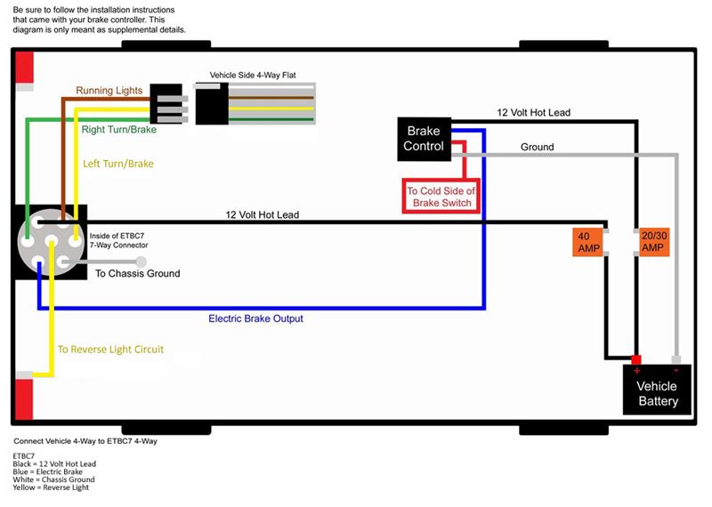
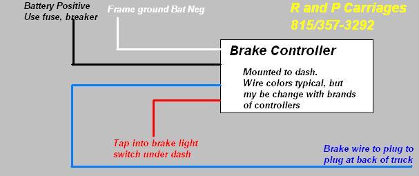
Warning reversing black and white wires or improper wiring will damage or destroy brake control. Journey brake control light green wire fig. Connect the desired trailer to the tow vehicle. Warning be sure to solidly connect all four wires or brake control will not function properly. Start the tow vehicle to ensure sufficient battery power is being supplied to the brake control. 4 factory pigtail brake control wire color wire color function red connect to black 12 volt positive light blue connect to red stop light black connect to white ground dark blue connect to blue trailer brakes brown not used white with red stripe connect to black 12 volt positive blue with white stripe connect to.
This is the valley journey electric brake controller. 4 factory pigtail brake control wire color wire color function red connect to black 12 volt positive light blue connect to red stop light black connect to white ground dark blue connect to blue trailer brakes brown not used white with red stripe connect to black 12 volt positive blue with white stripe connect to red.
Gallery of Journey Brake Controller Wiring Diagram