Back in the day fuzz faces had a deserved reputation for being variable in tone quality and what you hear may be what many guitar players heard when trying them out. This is the wiring diagram for the landtone fuzz face ac128 distortion pedal kit g161122pcb from ebay.

Original Pnp Germanium Fuzz Face Schematic Pedais De
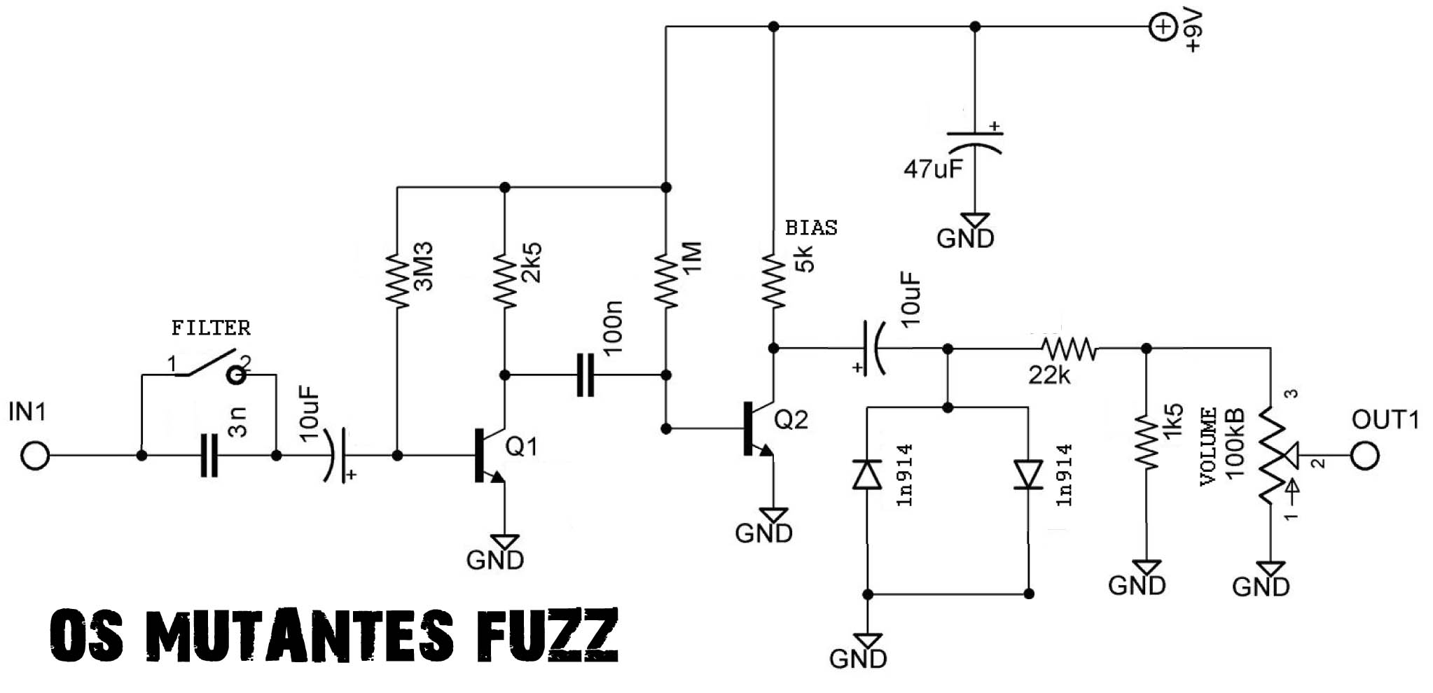
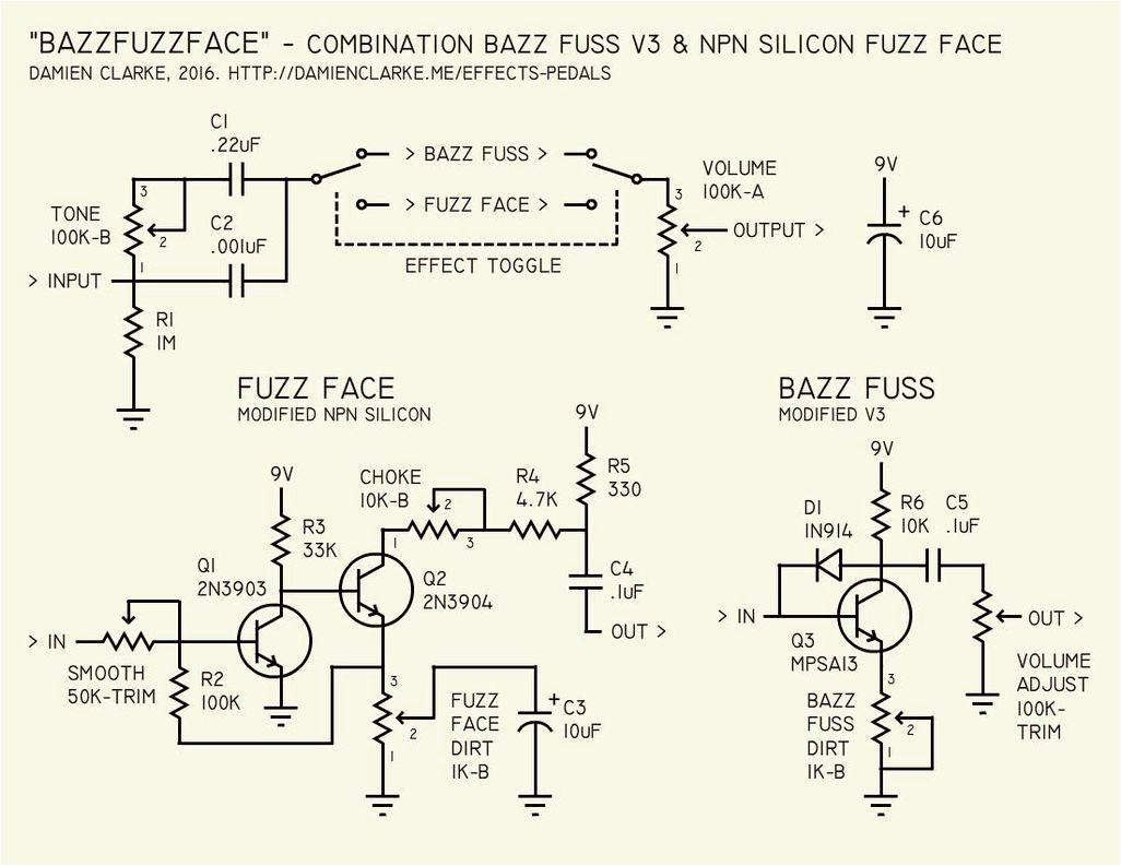
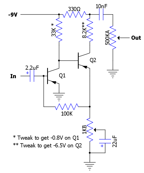
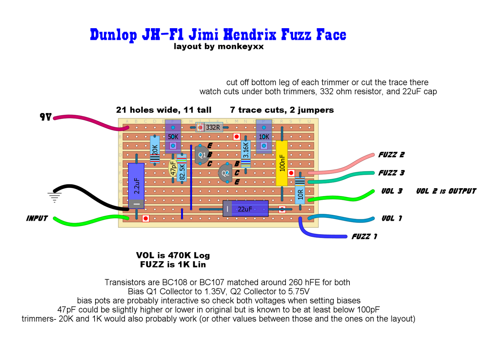
Fuzz face wiring diagram. The layout also uses a 10k trimpot on the collector of q2 so that that biasing can be adjusted preciselyaround 45vdc to 5vdc. I recently bought a used jh fuzz face pedal. One of the largest sites for do it yourself guitar effects builders. The fuzz e one small bear clone schematic. Otherwise we recommend you ignore this pcb mask and buy the ready to solder printed circuit board or complete kit from the links below. They would try many pedals till they found the one that sounded good.
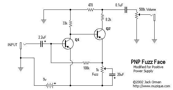
Here is a picture gallery about fuzz face wiring diagram complete with the description of the image please find the image you need. Here is the schem of the fuzz a tort. Schematics and printed circuit board layouts for rare pedals like the tycobrahe octavia clyde mccoy wah and lots of vintage fuzz pedals. Positive power for the pnp fuzzface with regard to fuzz face wiring diagram image size 562 x 291 px and to view image details please click the image. As you can see its the same basic idea but with a different biasing scheme for q2. It produces a characteristic high distorted sound called fuzz.
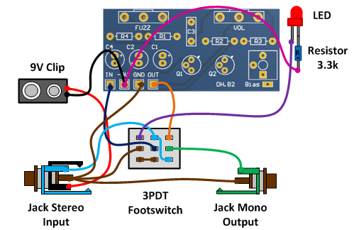
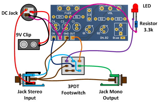
Ivor arbiter took the round shaped enclosure idea from a microphone stand and it was the first pedal including a dpdt stomp switch. Wire the pcb as shown in the diagram below. Make all connections to the back side of the pcb and solder on the top screen printed side of the pcb. Fuzz face ready for transfer printed circuit board layout for use only if you are a complete diy person who wants to etch and drill your own pcb. Finally a few people suggested emailing the vendor. Presuming there are no wiring errors lets look at possible tweaks.
Well it looks like someone got inside and changed some stuff around and some of the wires are not connect. Wiring flip pcb over. Unfortunately the kit doesnt come with directions. Make the wires as short as possible but allow enough length so that if you need to do any trouble shooting later you will. The fuzz face is a distortion guitar pedal designed in london by arbitrer electronics ltd in the autumn of 1966. The new fuzz face pcb and layout that i have drawn is based on the axis face circuit board which is quite possibly the smallest and most compact fuzz face circuit board available.
I have tested several sets of transistors in both circuits and i found that they work equally well with either biasing scheme. I searched online but theres not much information on how to hook up the 3pdt switch.
Gallery of Fuzz Face Wiring Diagram