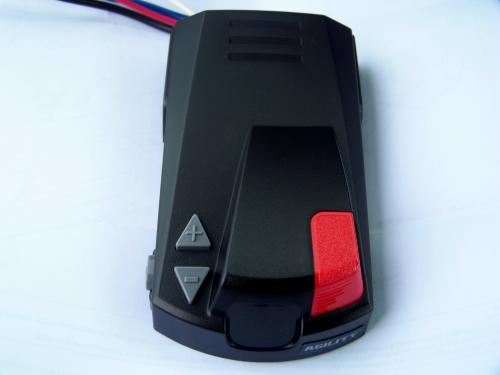
Find the wire by using a circuit tester and probing for the wire that powers the vehicle stoplights when the brake pedal is pressed. The built in digital display makes it easy for setting braking intensity.
Impulse Brake Controller Wiring Diagram Impulse Brake
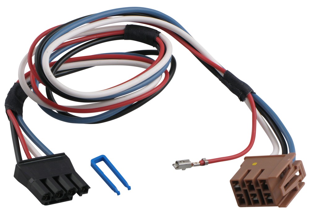
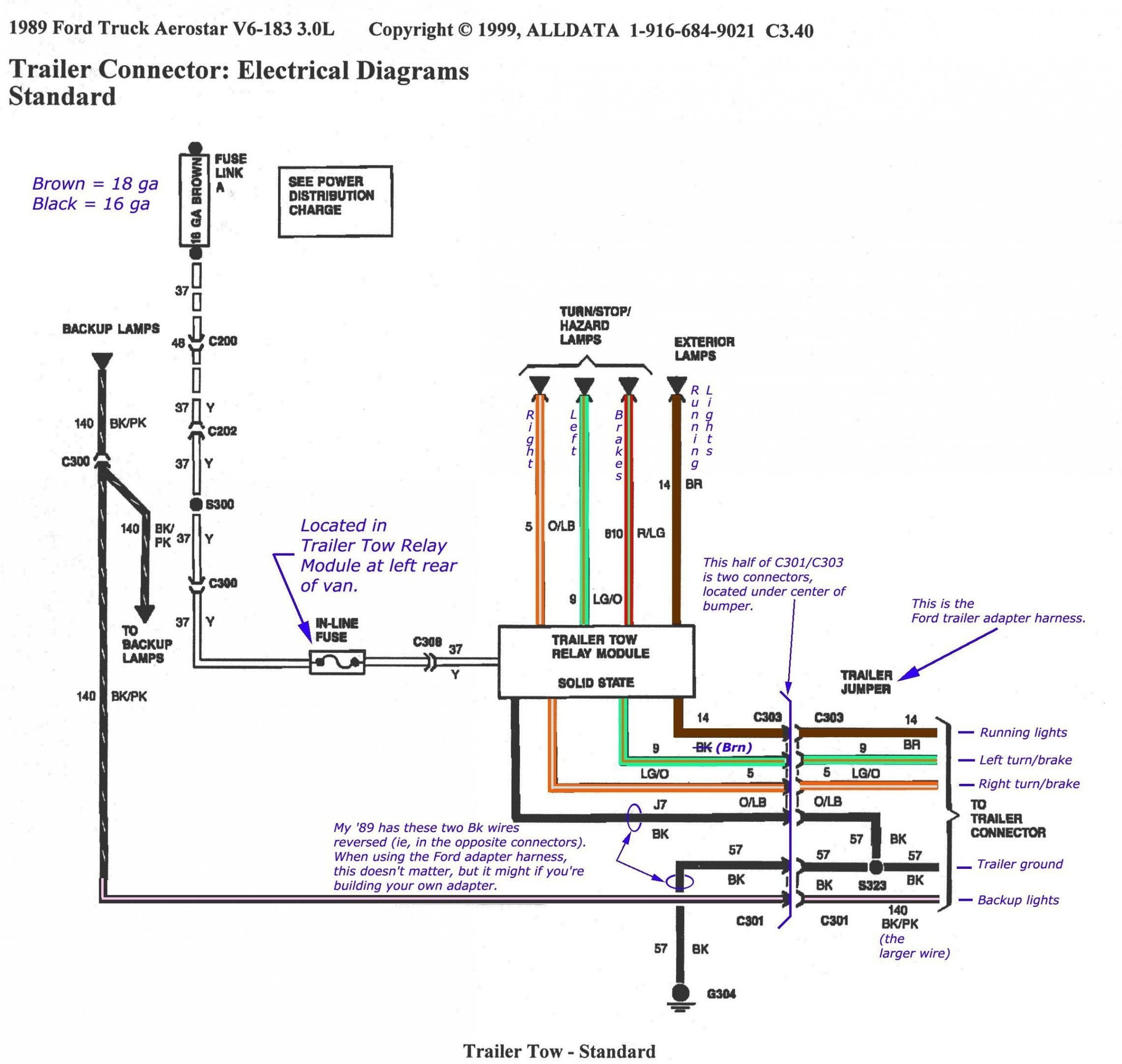
Impulse brake controller wiring diagram. Route blue wire from brake control to vehicle side. Wiring harness to install hopkins impulse brake controller in a toyota i have a toyota 4runner and an hopkins impulse break controller i just need to wiring diagram to install hopkins proportional brake controller in a from to gm trucks did not use plug in style brake controller wiring. Search for impulse trailer brake controller wiring diagram here and subscribe to this site impulse trailer brake controller wiring diagram read more. Keep these instructions with the brake control for future reference. Important facts to remember 1. Impulse trailer brake controller wiring diagram hopkins impulse trailer brake controller wiring diagram impulse trailer brake controller wiring diagram folks understand that trailer is a car comprised of very complicated mechanics.
Find your impulse trailer brake controller wiring diagram here for impulse trailer brake controller wiring diagram and you can print out. This car is designed not just to travel one place to another but also to take heavy loads. Read and follow all instructions carefully before wiring brake control. Splice red wire into cold side of vehicles stoplight switch located by the brake pedal. This article will be discussing impulse trailer brake controller. Route black wire from the brake control to the fuse or breaker.
Wiring instructions for electronic brake controls pn 4399 rev k generic wiring diagram read this first. The braking force to the trailer can easily be adjusted from 5 to 99 for setting the exact percentage of brake power desired. The brake control must be installed with a 12 volt negative ground. The 47235 brake control utilizes time based actuation for applying braking power to the trailer brakes.
Gallery of Impulse Brake Controller Wiring Diagram