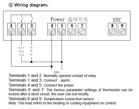
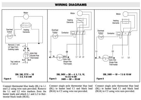
Heat trace wiring diagram. Ngutc 2030 and ngutc 2230.
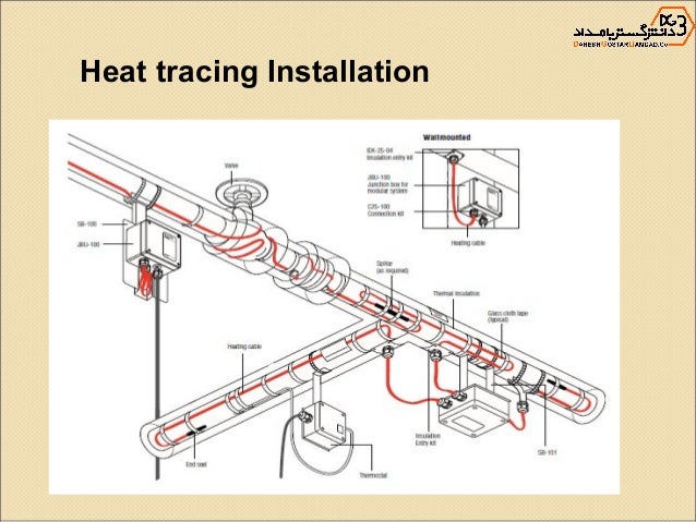
Heat Tracing Installation By Thermon
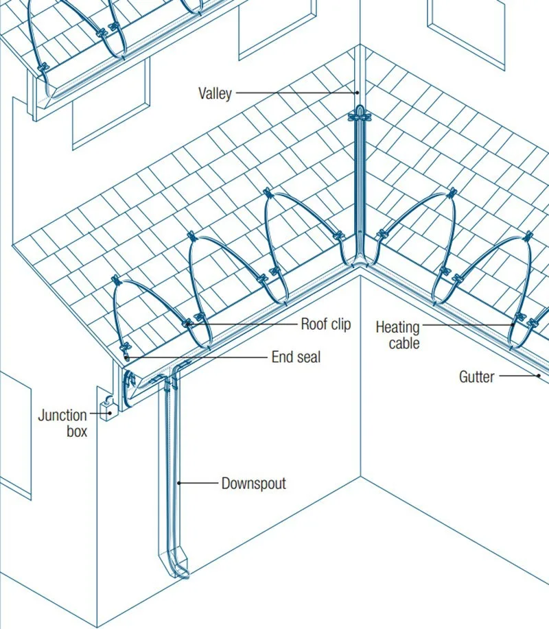
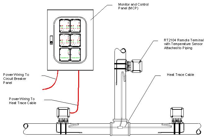
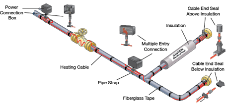
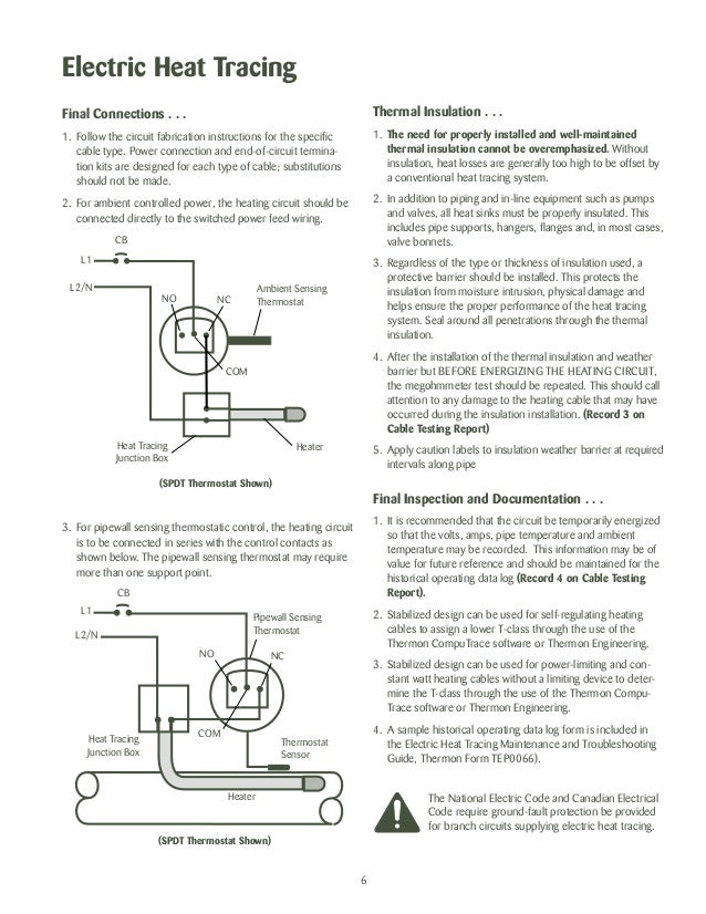
Heat trace wiring diagram. Isometric system diagrams if provided. Electric heat tracing. Heat trace pipes valves and flanges. Maintenance of electric heat tracing systems shall conform to all iec requirements for the use of electrical equipment and with the requirements of the relevant heat tracing standard usually either iec 62395 electrical resistance trace heating systems for industrial and commercial applications or iec 60079 30 explosive atmospheres electrical. The intellitracetm itc fs1 and itc fs2 provides the. Xl trace heat tracing systems carry agency approvals for the different applications shown in section 12.
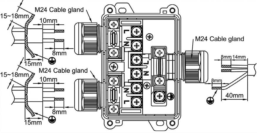
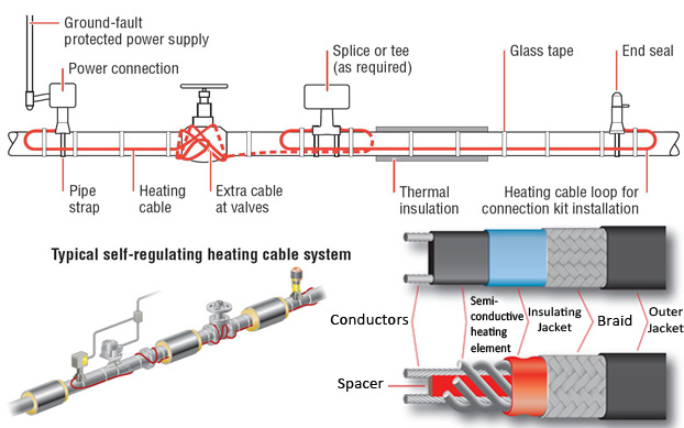
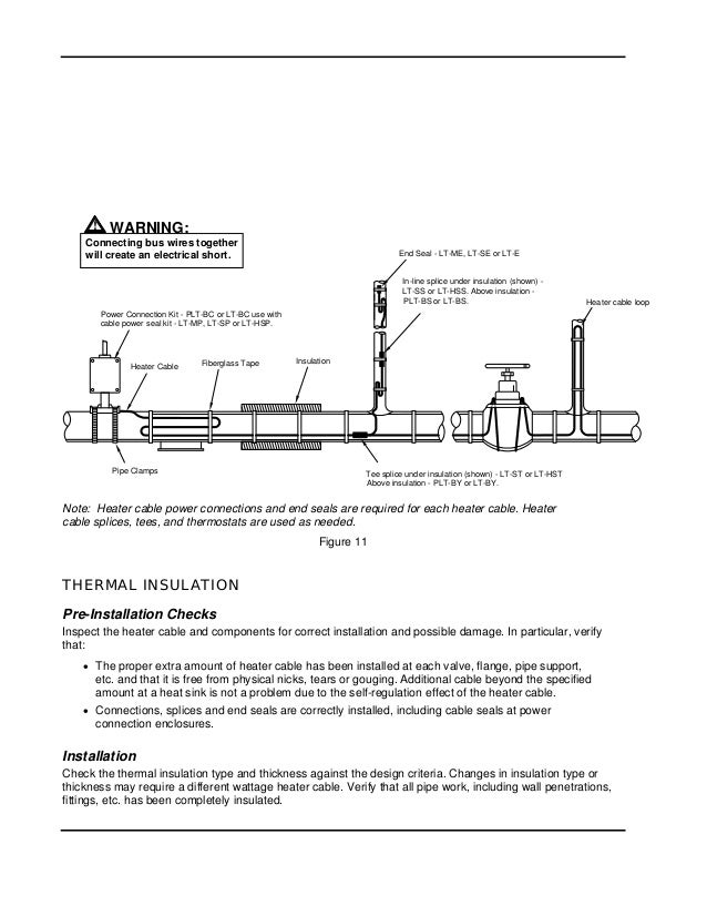
Wrap bands of tape around the trace heater and pipe at intervals of 12 30 cm or less keeping the trace heater in close contact with the pipe. Assortment of heat trace wiring diagram. Wiring diagrams comprise a couple of things. These are a com plete temperature control and system management so lutions for electrical heat trace applications. Lay out the trace heater on the pipe at the 4 or 8 oclock position illustration b securing it tightly against the pipe with attachment tape. 208 volts 277 volts 2703 2 75 128 2705 2 86 116.
Heat loss calculations and system design. The intellitracetm family of heat tracing products continues to expand with its latest single or two circuit controllers the itc fs1 and itc fs2. Assortment of heat trace wiring diagram. A wiring diagram is a simplified traditional photographic depiction of an electrical circuit. Heat and control products. Power adjustment factor part no.
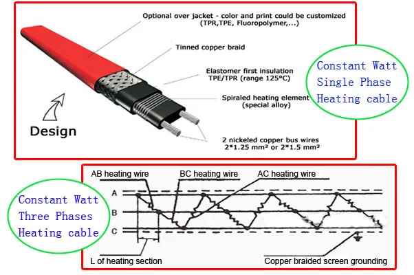
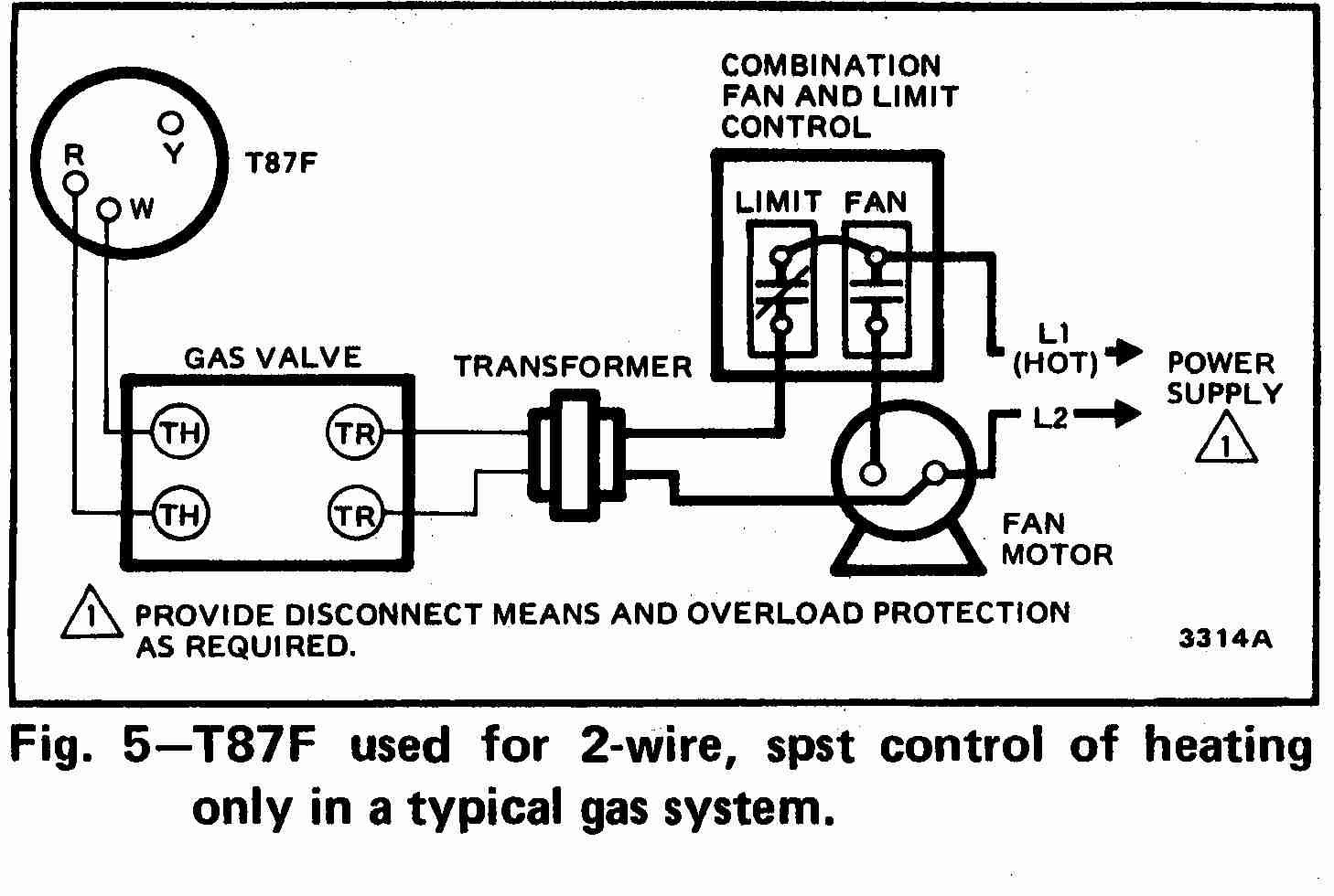
Heat trace wiring diagram whats wiring diagram. Symbols that represent the components inside circuit and lines that represent the connections together. It reveals the components of the circuit as simplified forms and also the power and signal links in between the devices. A wiring diagram is a simplified standard photographic depiction of an electrical circuit. Alternate voltages rscc 240 vac self regulatingheating cables can be operated at alternative voltages. The chart below compares heating cable power output with prod uct rating.
Warranty pentair thermal management standard limited war. A wiring diagram is a kind of schematic which uses abstract pictorial symbols to show each of the interconnections of components in a system. For detailed information on which approvals are carried for the specific applica tion refer to the pipe freeze protection and flow maintenance design guide h55838. It shows the elements of the circuit as simplified forms as well as the power as well as signal links in between the devices.
Gallery of Heat Trace Wiring Diagram