Narva bl voltage sensitive relay 12v vsr isolator a dual battery system. High current capacity automatic connectdisconnect and simple installation.

Charging Dual Battery Switch Wiring Diagram Power Sloer
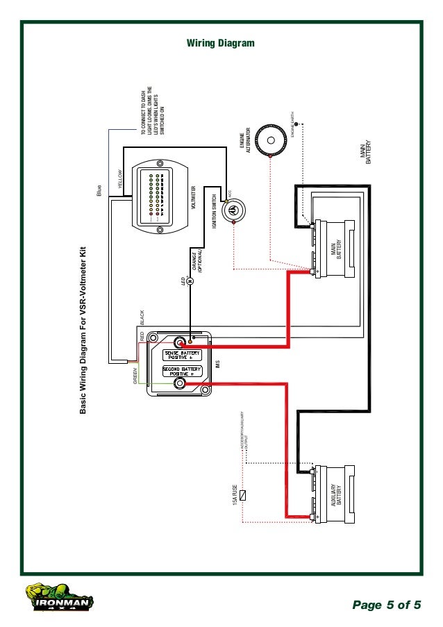
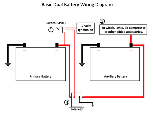
Dual battery vsr wiring diagram. It is intended to help all the average person in developing a proper method. Dual battery isolator wiring diagram for integrator1 jpg in system dual battery isolator wiring diagram. Cut attach the insulated ring terminal to the black wire on the vsr. Terminal of the starting battery be careful to keep the wiring away from any moving parts. 2 3 connect the thin black earth wire from the vsr to the vehicle chassis or the starter batterys negative. Free fast secure shipping authorised.
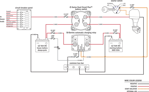
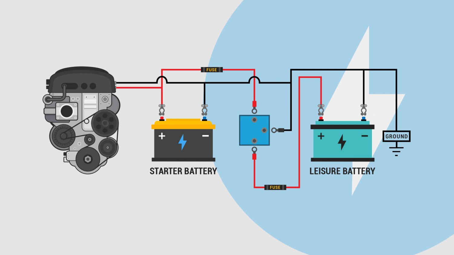
Having looked at several wiring diagrams for a cross section of. 4 connect the positive ring terminal of the included long cable to the unmarked silver terminal of the vsr. Wiring diagram will come with numerous easy to adhere to wiring diagram instructions. A typical 12v voltage sensitive relay vsr campervan wiring diagram. It means that when the leisure batteries are charging by solar panels or an ac battery charger and it is above 132v the vsr will automatically engage which will then charge the crank battery. A vsr will connect the aux battery when charging voltage is sensed at the main battery.
Vsrs are usually dual sensing. Connect the positive wire coming from the circuit breaker to the terminal on the vsr marked red. Wiring diagram for dual battery system with voltage sensitive relay isolator. These directions will be easy to comprehend and implement. Vsrs are popular for several good reasons.
Gallery of Dual Battery Vsr Wiring Diagram