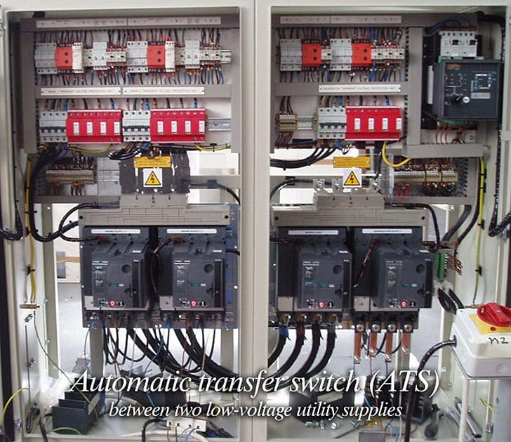
Connecting the current transformers after the mains and generator changeover will allow you to read and monitor the current when the load is connected to the power utility. Generator control panel wiring diagram.
Dg Synchronisation Process
Dg panel wiring diagram. 46512 46565 41535 and 41552 wiring diagram. This diagram illustrates some of the most common circuits found in a typical 200 amp circuit breaker service panel box. Bek3 zero amf controller bek3 canbu amf controller. The hot wire for a branch circuit is connected to the. Es52 wiring diagram gsc300 wiring diagram. Variety of generator control panel wiring diagram.
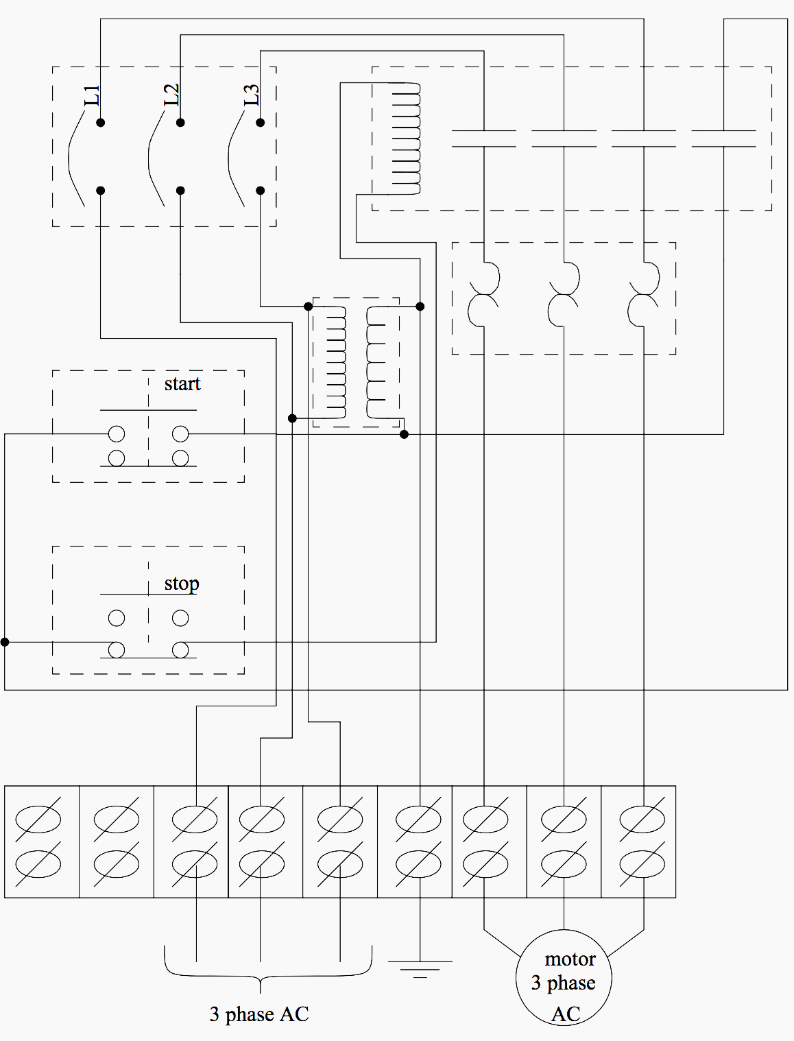
The breakers are installed in a panel so that contact is made with one of two hot bus bars running down the middle of the box. Note that symbols are discussed in detail later. Oct 3 2017 diesel generator control panel wiring diagram engine connections. This system uses 3 phase ac power l1 l2 and l3. Diesel generator control panel wiring diagram. The above illustrated diesel generator control panel wiring diagram is the typical connection wiring diagram of the bek3 automatic mains failure controller.
Eps engine power source eps 20kw diesel wiring diagram eps 2120 diesel generator wiring diagram eps 2277 diesel generator wiring diagram eps generator with smart start system. Diesel generator control panel w. Circuit breaker panel box wiring diagram. An example of a wiring diagram for a motor controller is shown in figure 1. It reveals the components of the circuit as streamlined forms as well as the power as well as signal connections between the gadgets. A wiring diagram is a streamlined traditional photographic depiction of an electric circuit.
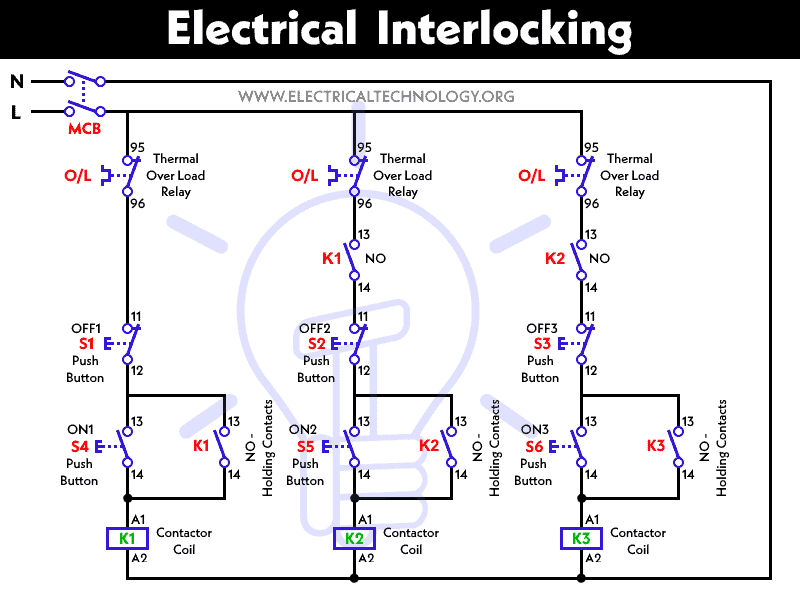
Dashed lines indicate a single purchased component. Electrical wiring diagrams of a plc panel.
Gallery of Dg Panel Wiring Diagram