Other wiring diagrams can be found here. 4 wire motor diagram wiring diagram show architectural wiring diagrams proceed the approximate locations and interconnections of receptacles lighting and unshakable electrical services in a building.
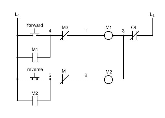
Motor Control Circuits Ladder Logic Electronics Textbook
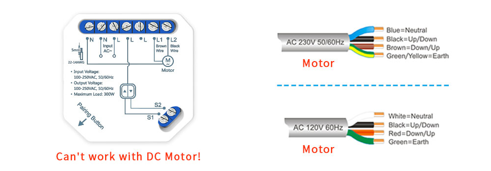
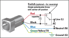
Dc motor wiring diagram 4 wire. Again this is ac power and not a dual capacitor so the terminal side does not matter brownwhite wire to the other side of the capacitor. A lower rating will decrease the current carrying capacity of the wire. White wire from the condenser fan motor to one side of power on the contactor t1 black wire from the condenser fan motor to other side of power on the contactor t2 brown wire from the condenser fan motor to the capacitor. In addition the dc wire selection chart shown below assumes a wire insulation rating of 105c. Motor connection diagram for a 4 wire reversible psc. Use figure 2 if your motor has a dual voltage shunt field.
Now for your 4 wire method. Use figure 1 if your motor has a single voltage shunt field. Interconnecting wire routes may be shown approximately where particular receptacles or fixtures must be on a common circuit. Choosing the correct wire a locate the current in amps of your appliance across the top of. Electric motor wire marking connections. Dc motor wiring diagram 4 wire.
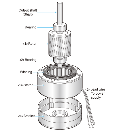
Dc motor wiring diagram 4 wire wiring diagram is a simplified gratifying pictorial representation of an electrical circuit. A wiring diagram is a streamlined conventional pictorial representation of an electrical circuit. Motor connections your motor will be internally connected according to one of the diagrams shown below. It reveals the parts of the circuit as streamlined forms as well as the power and signal links between the gadgets. These connections are in accordance with nema mg 1 and american standards publication 06. Not sure how it works i know that it did work in the treadmill that it came out of looking for some advice on how to wire it.
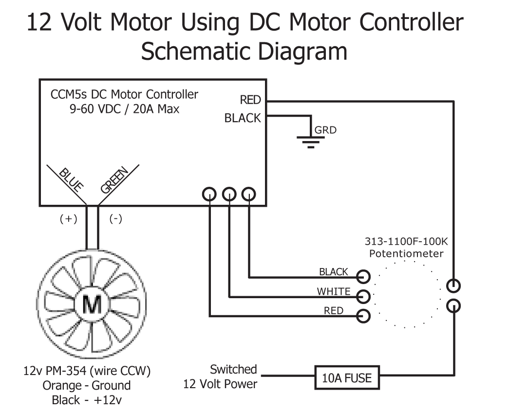
Collection of dc motor wiring diagram 4 wire. Motor wiring diagram dc. To use the chart included with this technical brief follow the instructions below. Schematic shows cw rotation facing the drive end. Three phase see below single voltage. For specific leeson motor connections go to their website and input the leeson catalog in the review box you will find connection data dimensions name plate data etc.
Schematic wiring diagram for dc electric motor connections. In the split series three wire reversible type universal motor one stator coil is used to obtain one direction and the other stator coil to obtain the other direction with only one stator coil being in the circuit at a time. It shows the components of the circuit as simplified shapes and the capacity and signal associates amongst the devices. For groschopp 115 and 230 volt ac80 ac90 and ac100 single phase motors. For ccw rotation transpose the blue and yellow leads.
Gallery of Dc Motor Wiring Diagram 4 Wire