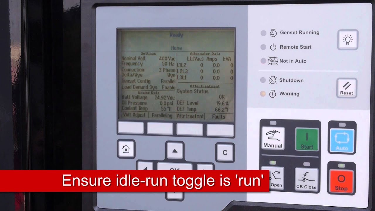
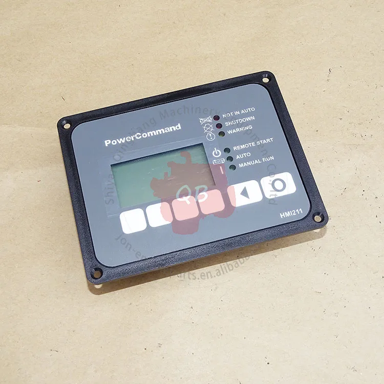
Power command hmi211 wiring diagram included on the instruction sheet the cummins power command controller hmi 211 provides a convenient and robust alternative to the standard generator mounted hmi 211 operator panel. Pcc 1302 terminal blocks tb1 and tb15 6.

A08fb1 5kw Onan Rv Generator Wiring Diagram For 6 Wiring
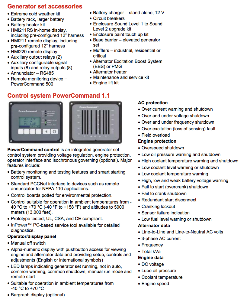
Cummins power command hmi211 wiring diagram. The powercommand control system is a power for this control system is derived from the generator set starting batteries. Kit includes the power command controller hmi 211 harness and instruction sheet. The hmi 211 can be powered from pcc 1302 if within 500 feet 152 meters. It is power command hmi wiring diagram if you like to secure all of these fantastic pictures related to power command hmi wiring diagram click on save link to save the graphics to your pc. If greater than 500 feet power must come from an. Description 1 tb15 2 tb1 figure 4.
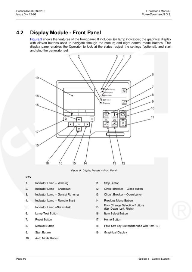
Power command hmi211 wiring diagram included on the instruction sheet the cummins power command controller hmi 211 provides a convenient and robust alternative to the standard generator mounted hmi 211 operator panel. See the wiring schematic in figure 5. The wire size required depends upon the distance between the two connections. Powercommand controller owners manual try the power command hmi wiring diagram and follow every detail in the picture. Wiring and terminal block customers need to supply wiring to connect the re mote hmi to the controller or the separate power supply. 1 j1 and j2 wiring connectors 2 p1 harness plug figure 3.
16 awg 131mm2 is the largest wire that can can be brought into the hmi socket contact pins. Connecting the hmi 211 remote no.
Gallery of Cummins Power Command Hmi211 Wiring Diagram