Most boats make provisions in their wiring for adding in an ammeter. Also known as an ammeter this is one of the instruments that has largely been replaced with an idiot light.

Cy 4748 Amp Gauge Wiring Diagram Ford Generator Free Diagram
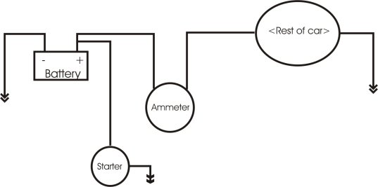
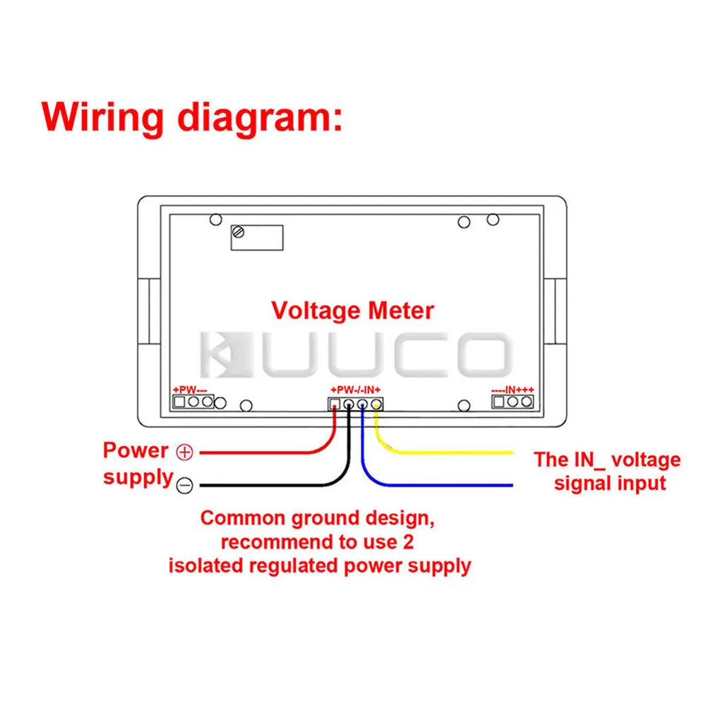
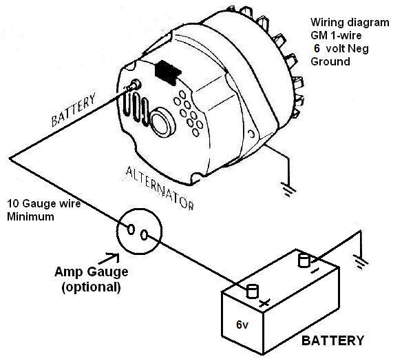
Ampere gauge wiring diagram. Amp gauge wiring 1 always disconnect the ground lead from the vehicle battery before wiring any gauge. Connect ammeter lamp 60 0 60 i only to existing instrument panel lighting circuit. The amp gauge. Ampere gauge wiring diagram ammeter gauge wiring diagram amp gauge wiring diagram ampere gauge wiring diagram every electric arrangement is made up of various different parts. Details of the wiring system and ammeter installation wiring diagrams. It reveals the elements of the circuit as simplified forms and the power and signal connections between the devices.
A wiring diagram is a simplified traditional photographic representation of an electric circuit. If ammeter shows a positive charge when starter is engaged reverse connections on back of ammeter. If not the structure wont function as it should be. Assortment of volt amp meter wiring diagram. Install an amp gauge in your car and you will instantly know the general condition of your vehicles electrical system. Each component ought to be placed and linked to other parts in particular manner.
It is recommended that insulated wire terminals preferably ring type be used on all connections to. Be certain to use stranded insulated wire not lighter than 10 awg that is approved for marine use. Without it you will not know there is a problem until it is too late. 2 classic instruments amp gauge should only be used on vehicles with alternators rated at 60 amps or less. Reconnect the battery ground cable. Using an alternator with higher output capacity is dangerous and could cause a fire.
Gallery of Ampere Gauge Wiring Diagram