Wholesaler copeland ge pn pick up drop out cont. Potential relay wiring diagram compressor potential relay wiring diagram copeland potential relay wiring diagram mars potential relay wiring diagram every electrical arrangement consists of various distinct components.

Basic Electrical Controls Of Air Conditioning Units
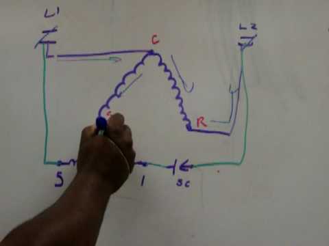
Copeland potential relay wiring diagram. A5 terminal box compressor. Winding with start and run capacitor and potential relay. It consists of directions and diagrams for different varieties of wiring methods as well as other things like lights windows and so forth. It reveals the components of the circuit as simplified forms and the power as well as signal connections between the tools. Ill shows two potential relays that look much like ordinary general purpose relays. It is very easy to miswire a compressor but the results can be deadly.
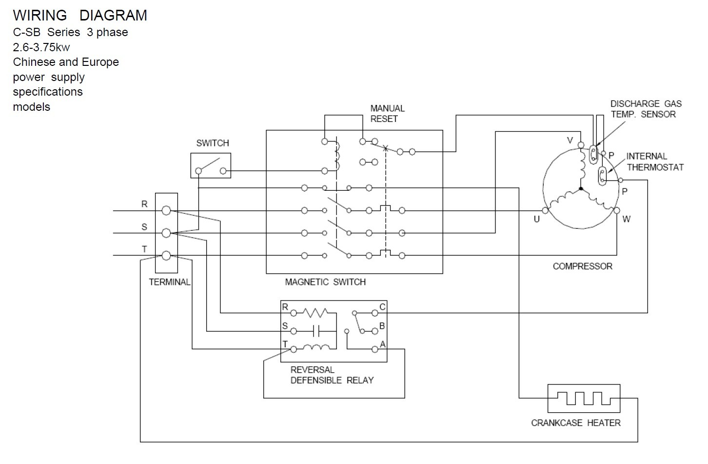
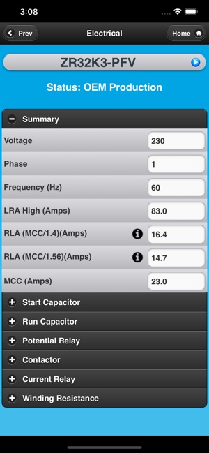
Copeland potential relay wiring diagram run capicator for manual e potential relay wiring diagram. Electrical wiring diagram tfd 3 phase. Copeland outdoor condensing unit. Pn brand pn volts volts rating potential relay data 940 0001 48 040 0001 48 3arr3kc7m5 150 160 15 45 130 60. Each part should be set and connected with different parts in particular way. A over current thermal protection switch in the terminal box for single phase.
If not the structure wont function as it should be. The use of a. Wiring diagram contains numerous in depth illustrations that present the relationship of assorted products. The purpose of this booklet is to dem onstrate how to wire a. Dwm copeland semi hermetic compressors are available for 50 andor 60 hz voltage supply. F10 thermal protection switch m2.
Mar 17 the potential relay is normally closed and it opens when a and common but this does not mean that wiring between start and run is bad it. The wiring diagram for a potential relay is shown in ill the potential. A wiring diagram is a streamlined traditional photographic depiction of an electric circuit. Variety of wiring diagram for copeland compressor. Accordance with the position of the capacitors and relay shown on the wiring diagram.
Gallery of Copeland Potential Relay Wiring Diagram