Dc v olt age 9. They show the relative location of the components.

Http Www 8thcivic Com Forums Diy Honda Civic Electrical
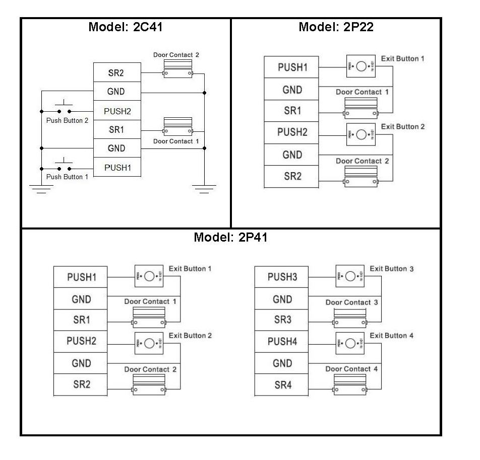
Button wiring diagram. They can be used as a guide when wiring the controller. This light switch wiring diagram page will help you to master one of the most basic do it yourself projects around your house. You will be able to know precisely when the projects ought to be accomplished which makes it easier for you to properly manage. Wiring diagram for a two chime doorbell wiring for two doors is the same as for one with the transformer hardwired to the 120 volt source from a house circuit. Some clamp on ammeters can read voltage and ohms. Figure 1 is a typical wiring diagram for a three phase mag.
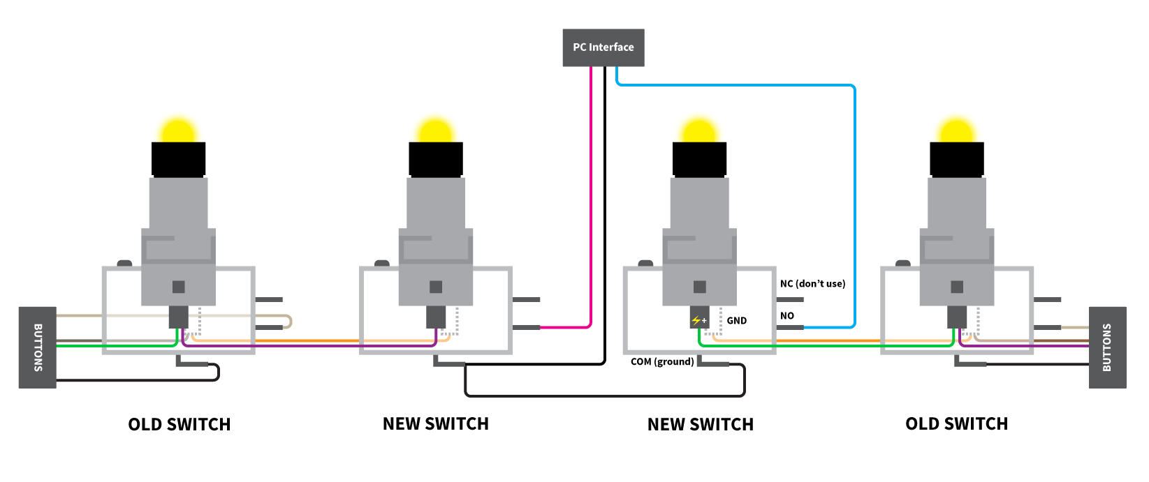
Troubleshooting for the 5 button 3109228001 comfort control center system a. When wiring a 2 way switch circuit all we want to do is to control the black wire hot wire to turn on and off the load. This site is merely. Black wire power or hot wire white wire neutral bare copper ground. You can also wire this circuit the opposite way with a pullup resistor keeping the input high and going low when the button is pressed. Use the drop down menu here to search for any product wiring diagram made by lutron.
Push button selector switch limit switch etc. Wiring a single pole light switch. Connect the other wire from the button to the other contact on the chime in the housing. This simple diagram below will give you a better understanding of what this circuit is accomplishing. The neutral from the source is spliced through to the switch box using the white wire and in this diagram the white wire is capped with a wire nut. Hey doing it yourself is great but if you are unsure of the advice given or the methods in which to job is done dont do it.
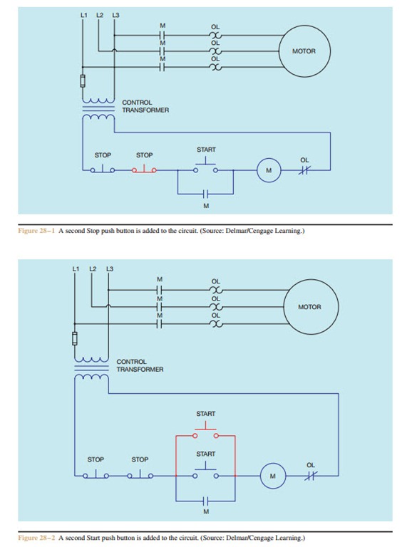
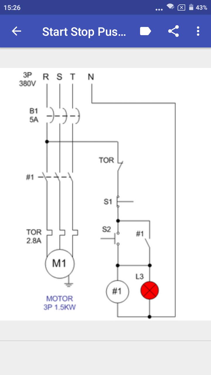
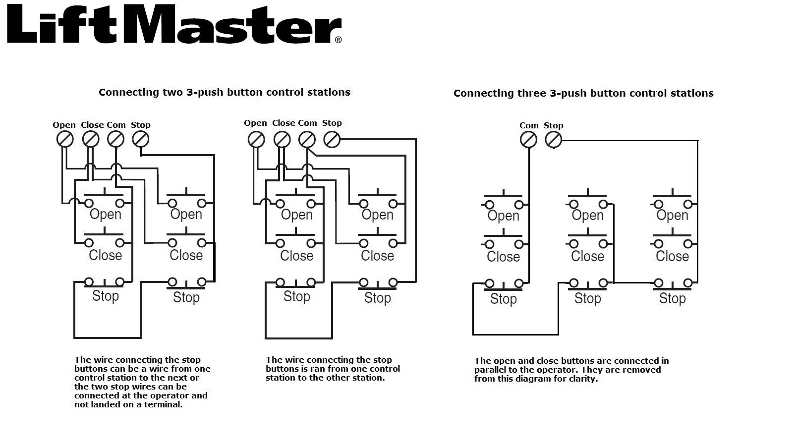
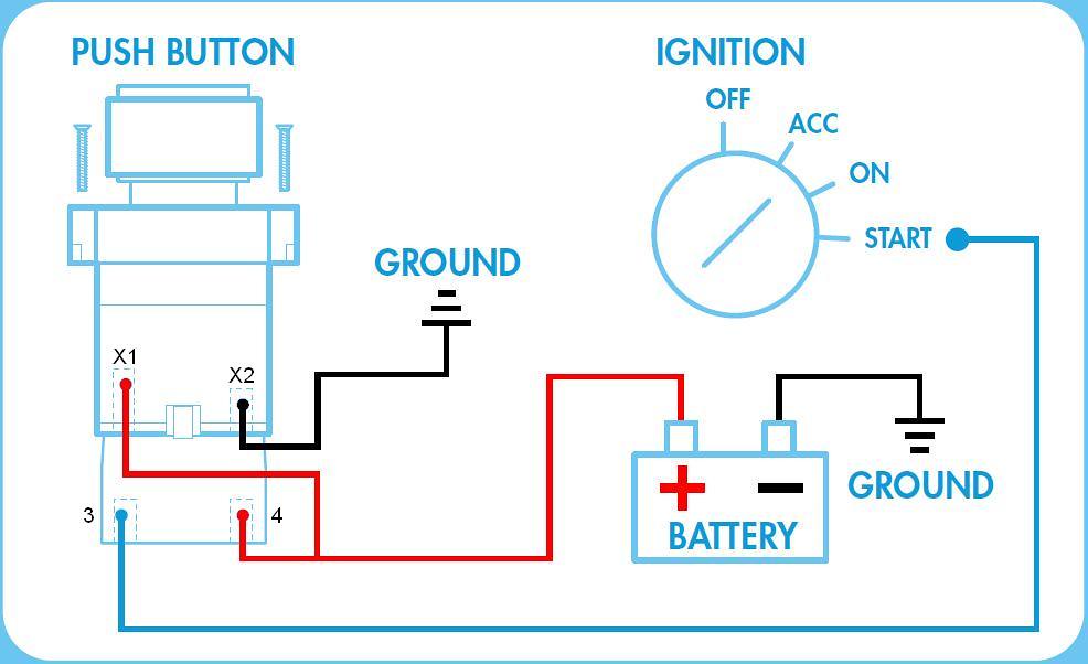
Push button switch wiring diagram perfect ignition relay wiring push button starter switch wiring diagram. Fiber optic cable electrical connections boundary seal to be in accordance with article 501 5 of the national electrical code hazardous locations nonhazardous locations. Wiring diagrams sometimes called main or construc tion diagrams show the actual connection points for the wires to the components and terminals of the controller. Furthermore wiring diagram gives you enough time frame in which the assignments are to become finished. Reversing v alve tools required the air conditioner can be checked with a voltmeter ohm meter clamp on ammeters and two good thermometers. When the button is closed pressed it makes a connection between its two legs connecting the pin to 5 volts so that we read a high.
In this updated diagram 3 wire cable runs between the receptacle and switch and the red cable wire is used to carry the hot source to the switch. Ac power module 17. Wiring diagram since wiring connections and terminal markings are.
Gallery of Button Wiring Diagram