Bcm 50 main unit wiring. Business communications manager 52 pages summary of contents for nortel bcm50.
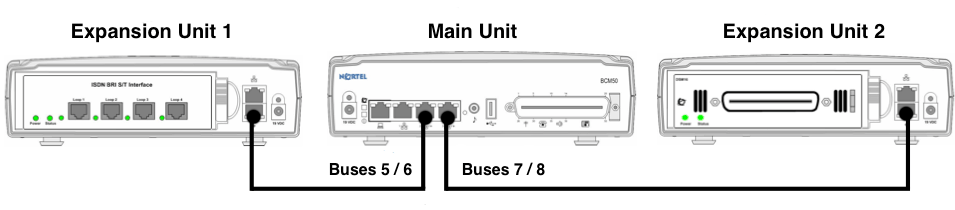
Bcm50 Expansion Unit
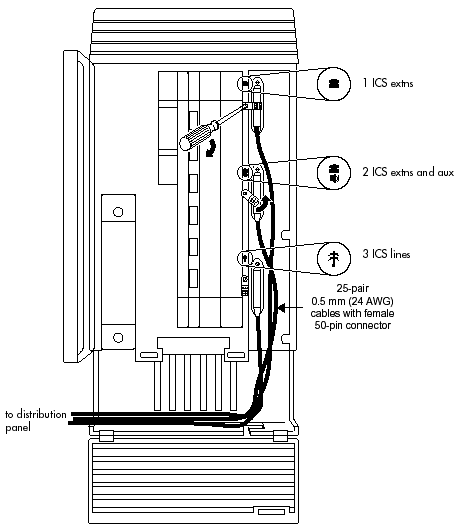
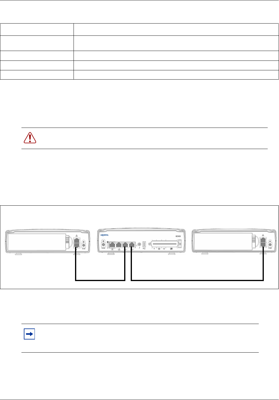
Bcm 50 wiring diagram. Into the cable management tray of the wallmount bracket and connects to the rj 21 telephony connector through a 50 pin header. Bcm50 components the power supply adapter cord is for international. The value next to the clock icon indicates the average time that it takes to complete the procedure. Gatm48 media bay module amphenol wiring. Use the tables and checklists to guide you through the installation process. L1 to l4 gatm8 nt5b44a supports 8 analog trunks.
You can connect 4 analog telephone lines 4 analog telephony devices and 12 digital telephones to the main unit. Main unit telephony ports. Page 11 installing the wiring field card optional. Gatm4 nt5b44b supports 4 analog trunks. L1 to l8 trunk modules are compatible with the bcm 200400450 main units and bcm 50400450 expansion units. Print this chapter to record the progress of the avaya business communications manager 50 avaya bcm50 system installation and configuration.
Bcm 50 main unit wiring list of figures figure 1 line of sight diagram. Pmp devices may receive ntp data from a cmm3 or cmm4 module or from an ntp server configuredwiring diagram below. Bcm50 wiring jandjcommunications bcm nortel bcm 50 wiring htm26 rows 1 888 552 6665 770 795 5462 shipping address 3600 a kennesaw n ind. Bcm 50 trunk module wiring.
Gallery of Bcm 50 Wiring Diagram