Because the aem gauge utilizes the internal aem uego controller and bosch uego sensor it is accurate and repeatable to 01 of an airfuel ratio point. 1 x bw uego gauge assembly.

Zl 8112 Aem Wideband O2 Sensor Wiring Diagram Aem Free
Aem afr gauge wiring diagram. Aem gauge type uego controller parts. Welcome to my blog here i will show you a little more what you are looking for aem 35 wiring diagram below there arefind best value and selection for your aem wideband o2. The aem gauge is ideal for all vehicles including carbureted applications and engine dynamometers. With this there is no abrupt oscillation as found in many competitor gauges which utilize a narrow band oxygen sensor detecting only stoichiometry. Aem 35 wiring diagram. Aem air diagram.
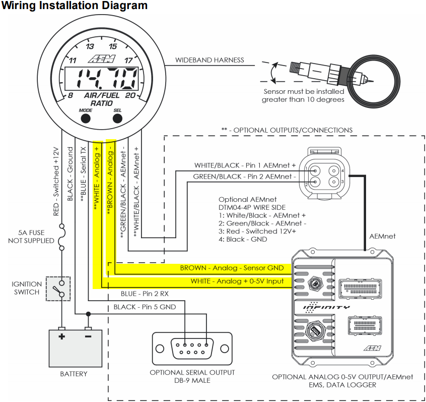
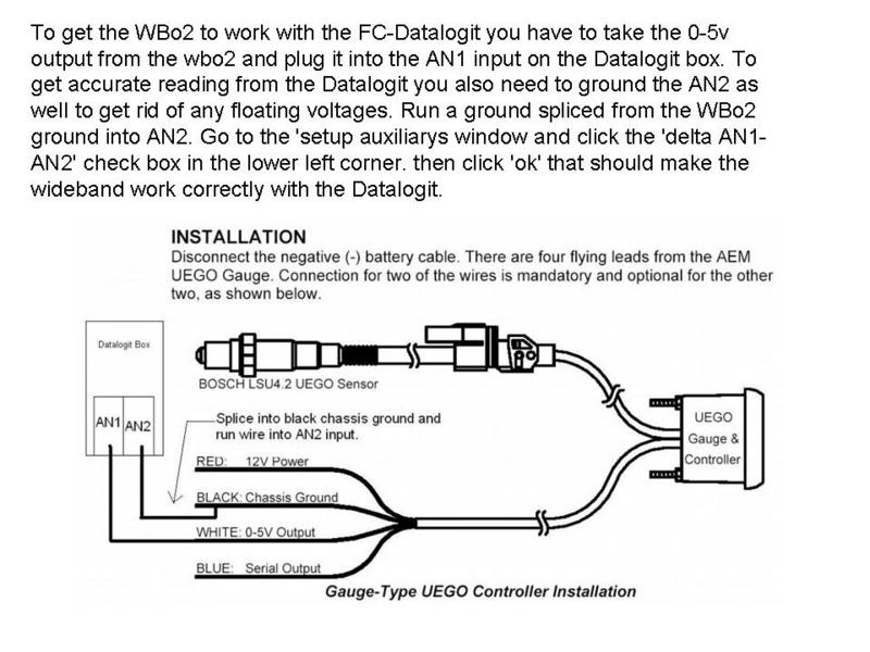
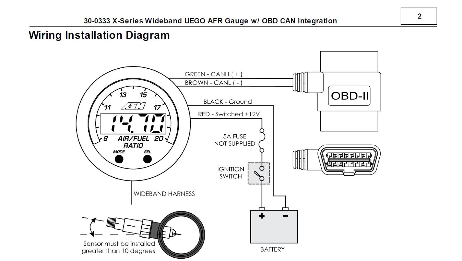
Analog wideband airfuel ratio gauge. Wiring schematic aem gauge type uego controller parts 1 x 35 5130bw uego gauge assembly 1 x 30 2001 uego sensor 1 x 35 8535 install kit o2 bung with 6 butt connectors 1 x 10 5130 installation instructions 1 x 35 3411 8 pin power harness 1 x 35 3400 6 pin sensor harness 1 x 35 8529s silver bezel. This particular photograph aem afr gauge wiring diagram aem 35 8460 wiring diagram wiring intended for aem air fuel gauge wiring diagram previously mentioned is usually labelled together with. The 52mm 2 116 aem x series universal exhaust gas oxygen uego gauge features a four digit central readout and sweeping 24 color coded led display providing immediate reference to the engine air fuel ratio or lambda in real time. Aem air fuel ratio gauge wiring diagram aem 400lph high flow in line fuel pump 50 1005 aem air fuel ratio gauge wiring diagram wiring diagram is a simplified enjoyable pictorial representation of an electrical circuit. Put up by means of tops stars team with may 3 2014.
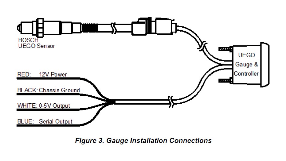
It shows the components of the circuit as simplified shapes and the power and signal contacts between the devices. Analog wideband airfuel ratio gauge figure 1.
Gallery of Aem Afr Gauge Wiring Diagram