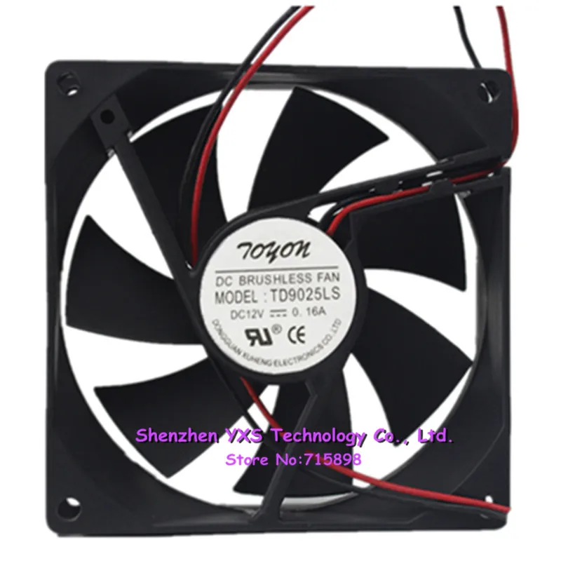
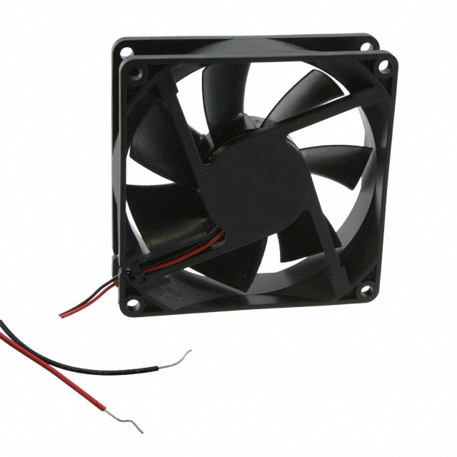
Dc 12v operating voltage. Modal full trailer wiring diagram for 4s3m and 6s3m.

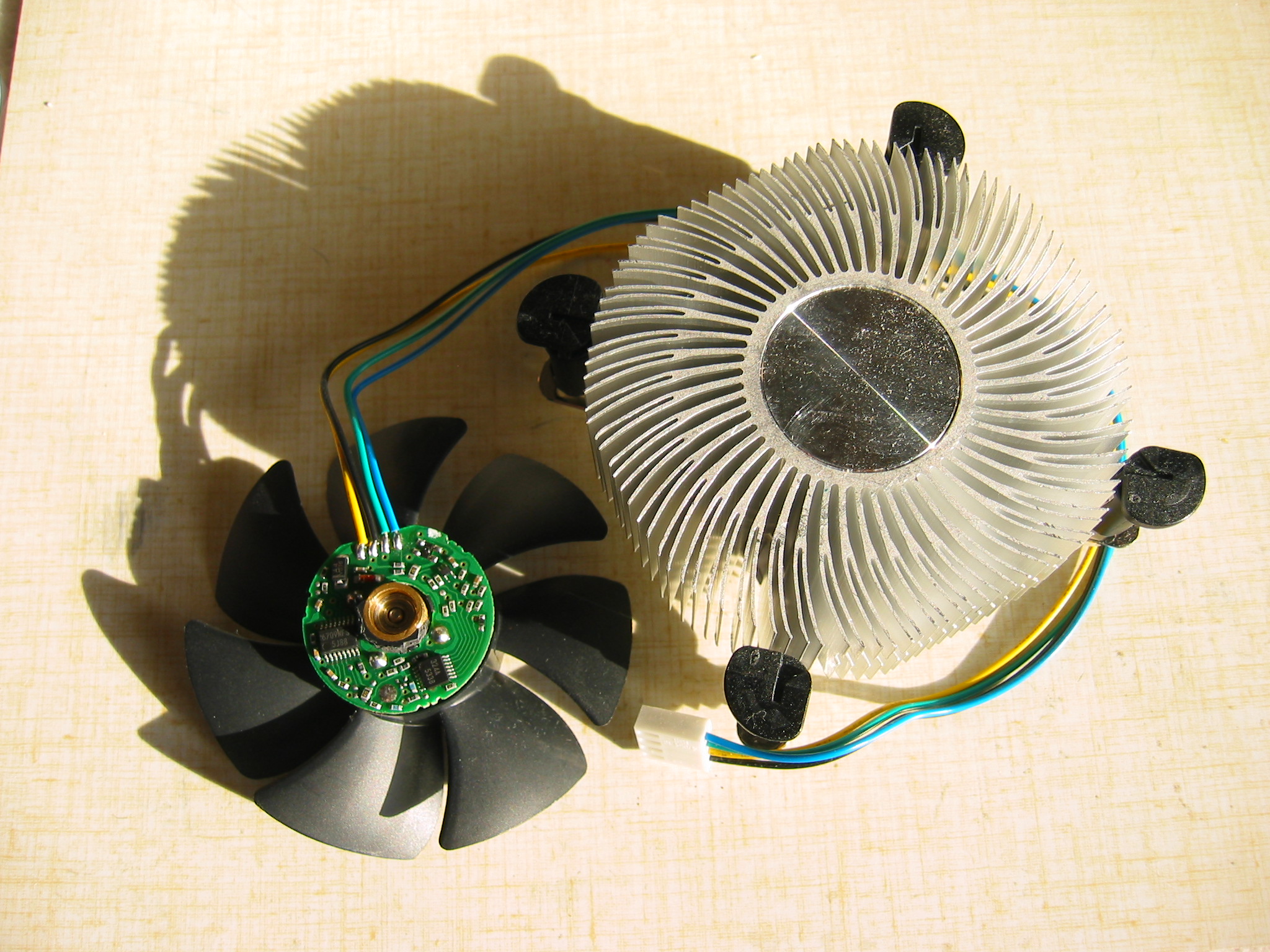
Wiring Up A Brushless Motor Fan
Aub0912vh wiring diagram. This diagram is to be used as reference for the low voltage control wiring of your heating and ac system. Used 4 wire fan for these two projects. Skip to the beginning of the images gallery. Always refer to your thermostat or equipment installation guides to verify proper wiring. Modal ecu connector and power supply details. Pricing and availability on millions of electronic components from digi key electronics.
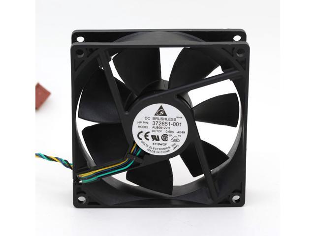
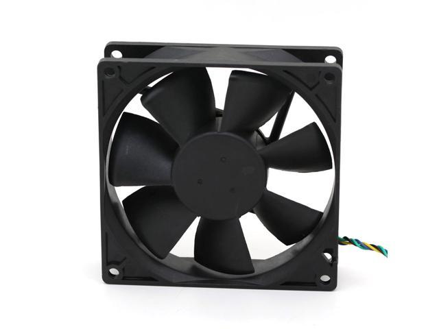
Audi fault codes dtc. A written request should be submitted to delta prior to approval if deviation from. Refer to the blower chart for cfm requirements. Aub0912vh cx09 fan tubeaxial 12vdc square 92mm l x 92mm h superflo 678 cfm 190m³min 4 wire leads from delta electronics. Delta aub0812vh 4 pin 80mm fan delta aub0812vh dimensions. Today this german company belongs to the car concern volkswagen.
Haldex abs modal ecu wiring diagrams. Delta will not guarantee the performance of the products if the application condition falls outside the parameters set forth in the specification. Automobile plant audi automobil werke began its work in 1909. Dc 108v 132v current. June 24 2009 application notice 1. Fmbg es form 001 rev.
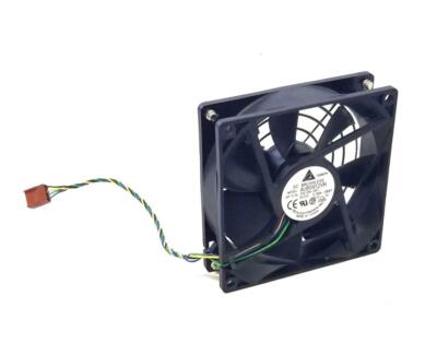
Modal semi trailer wiring diagram for 2s1m 12v system 72kb. Audi owner service manuals pdf above the page 80 100 200 allroad quattro a3 s3 a4 a5 a6 r8 rs2 rs4. Order today ships today. The ins and outs of a 4 wire computer fan. Note y2 some ac systems will have a blue wire with a pink stripe in place of the yellow or y wire. Online from elcodis view and download aub0912hh pdf datasheet fans ac specifications.
Mtbf aub0912vh cx09pdf skip to the end of the images gallery. Modal semi trailer wiring diagram for 4s3m and 6s3m. 4 wire leads ingress protection operating temperature 1060⁰c weight gram g 99g current rating. Audi one of the most recognizable in the world of automobile brands. Request delta electronics aub0912hh. 3ø wiring diagrams 1ø wiring diagrams diagram er9 m 3 1 5 9 3 7 11 low speed high speed u1 v1 w1 w2 u2 v2 tk tk thermal overloads two speed stardelta motor switch m 3 0 10v 20v 415v ac 4 20ma outp uts diagram ic2 m 1 240v ac 0 10v outp ut diagram ic3 m 1 0 10v 4 20ma 240v ac outp uts these diagrams are current at the time of publication.
The company was created after the departure of august.
Gallery of Aub0912vh Wiring Diagram