The following article explains an enhanced automatic transfer switch ats circuit which includes several customized sequential changeover relay stages making the system truly smart. How to dimension a panel how to manufacture panels how to interface a panel with a diesel generator.
2 Simple Automatic Transfer Switch Ats Circuits Homemade
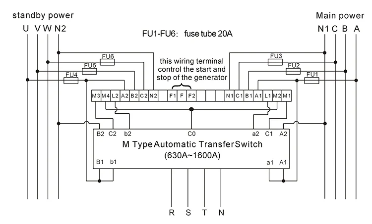
Ats control wiring diagram. It shows the elements of the circuit as streamlined shapes as well as the power and also signal links between the gadgets. It shows the components of the circuit as simplified shapes and the capability and signal contacts amid the devices. The contactors are not allowed to close simultaneously but only one at a time. Fig 5 shows 4 poles 3 phase automatic transfer switch ats connection to the main distribution board. It is about two electrically controlled circuit breakers. Yu will find lessons of full immersion in the automatic mains failure and automatic control panel matter.
A wiring diagram is a simplified conventional photographic depiction of an electric circuit. It shows the parts of the circuit as streamlined shapes as well as the power and signal links in between the gadgets. A wiring diagram is a streamlined conventional pictorial representation of an electric circuit. All the wiring connections are same as above for manual operation of three phase changeover switch but the switching operation is automatic. Learn about ats control panel wiring diagram. A smart way to build an automatic transfer switch is by using two contactors together with an ats controller.
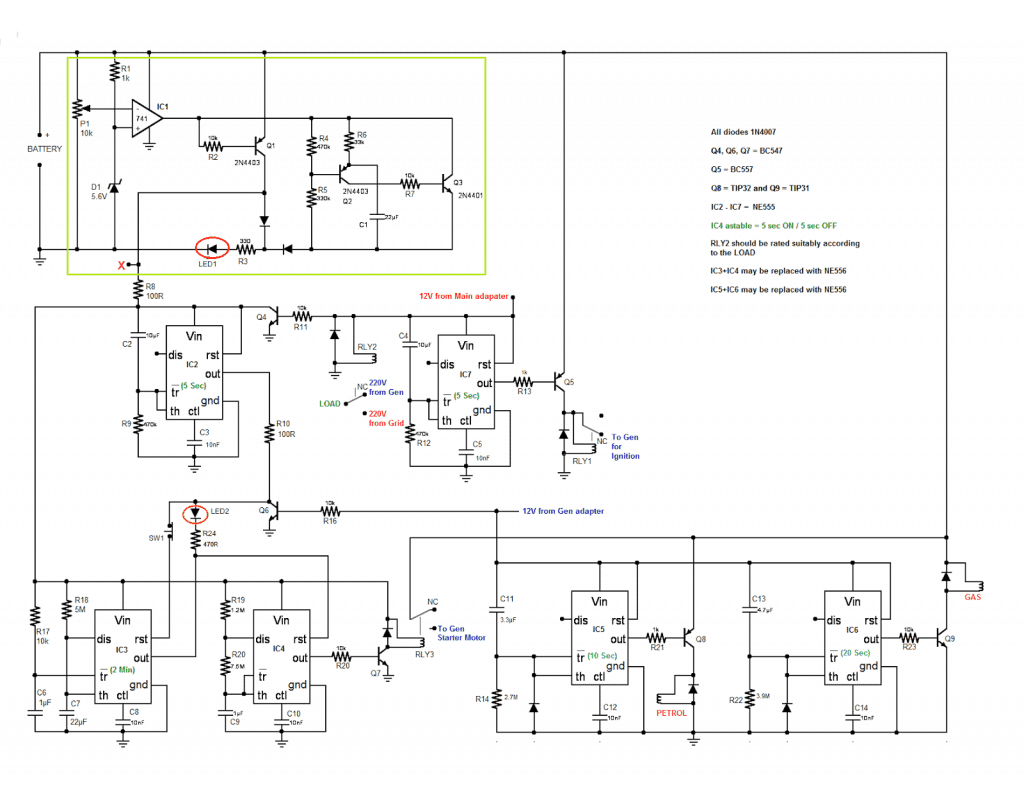
February 28 2019 by larry a. Purchase the how to make amf ats panes. Wellborn variety of ats wiring diagram for standby generator. Wellborn assortment of asco 7000 series ats wiring diagram. September 11 2018 by larry a. Updated ats circuit diagram with complete ic 4060 and ic 555 wiring details.
Ats control wiring diagram wiring diagram is a simplified adequate pictorial representation of an electrical circuit.
Gallery of Ats Control Wiring Diagram