Accuair wiring diagram wiring diagram is a simplified standard pictorial representation of an electrical circuitit shows the components of the circuit as simplified shapes and the talent and signal connections amid the devices. This is just a quick rundown of some of the features of the new valve block and comparisons to accuairs older vu 4 model.
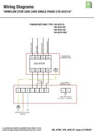
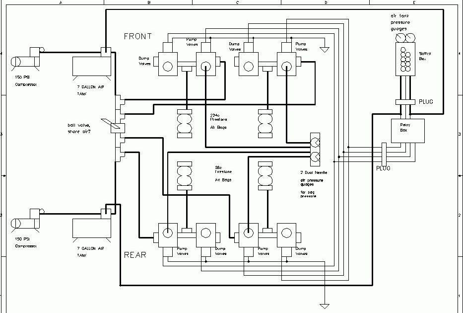
Wiring Diagram Billet Rev 3 Air Suspension
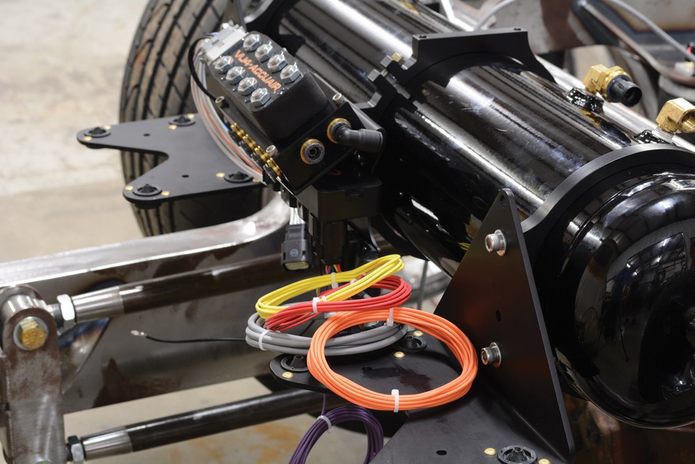
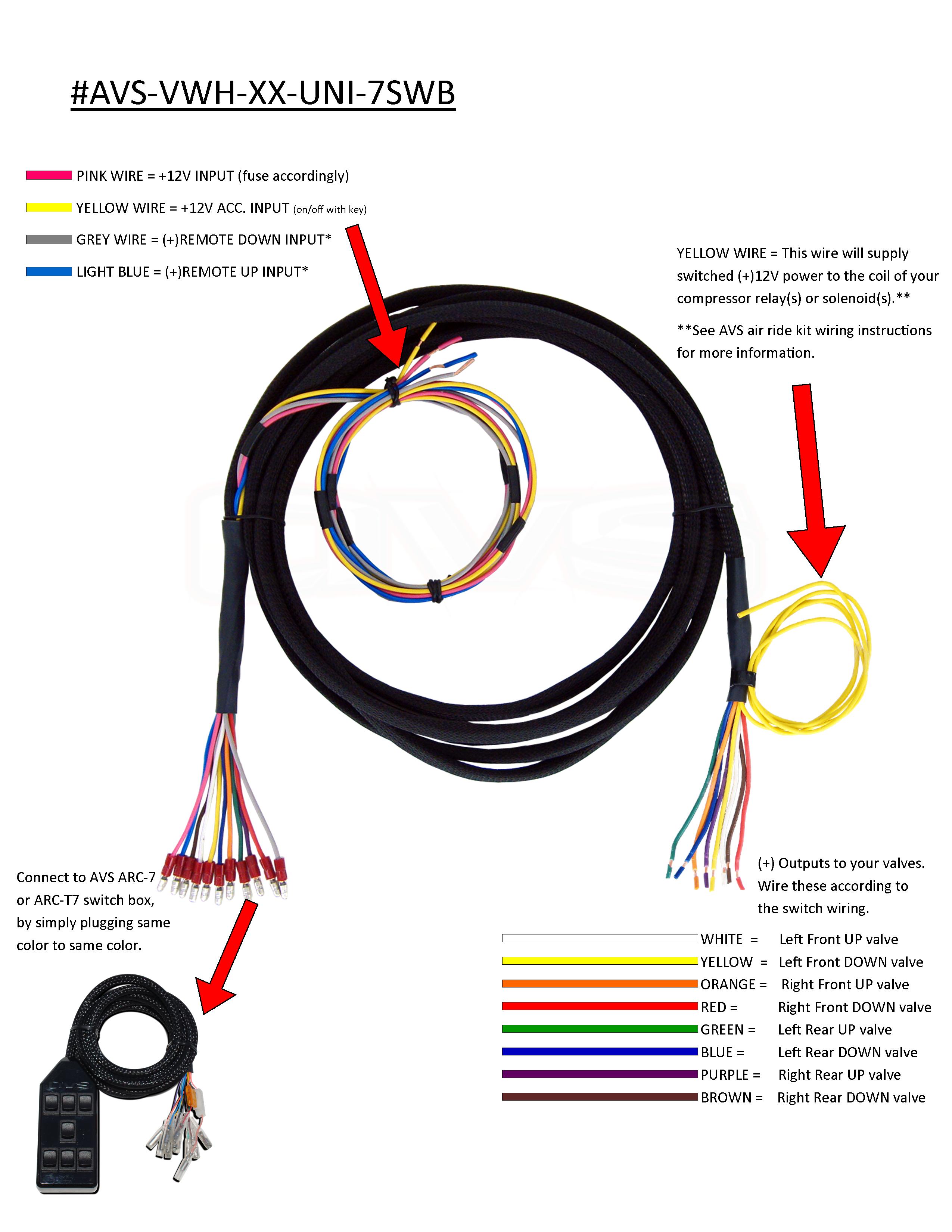
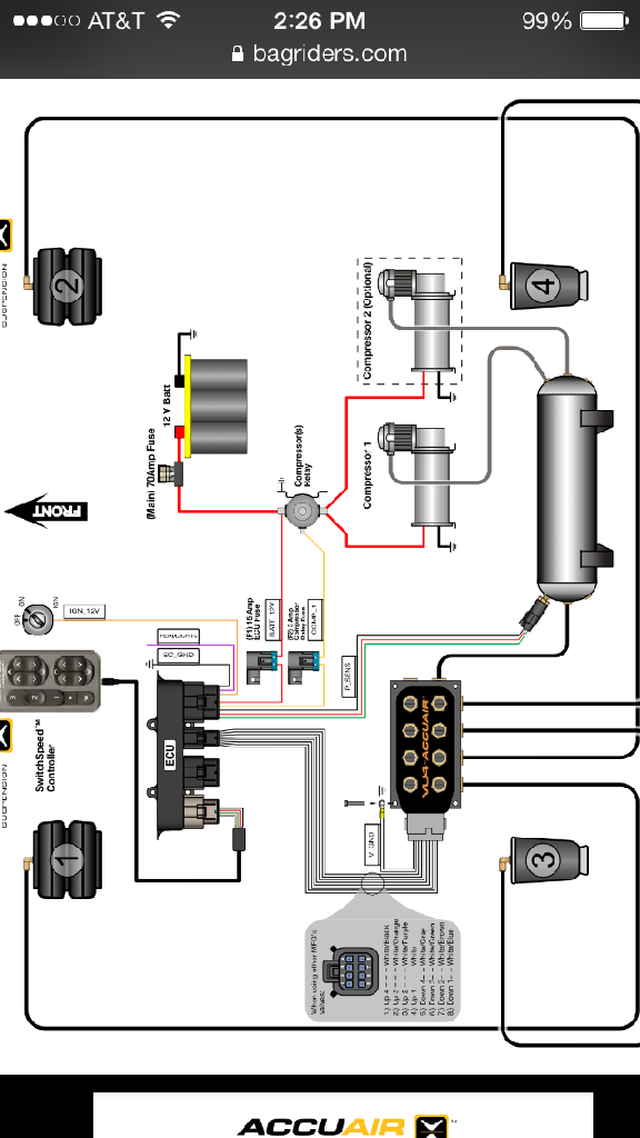
Accuair vu4 wiring diagram. 4 place the ground eyelet from the vu4 wiring harness under one of the cap screws and make sure that this screw has good contact to chassis ground. Remote fill and dump wires for your avs arc 7 switch box are also included in the harness. 3 drill holes with a 316 drill bit and bolt the vu4 down with the included 10 24 allen head cap screws. A wiring diagram usually gives instruction just about the relative point and union of devices and terminals on the devices to back up in building or servicing the. 3 drill holes with a 316 drill bit and bolt the vu4 down with the included 10 24 allen head cap screws. 2 transfer hole pattern from the vu4 mounting template on page 14.
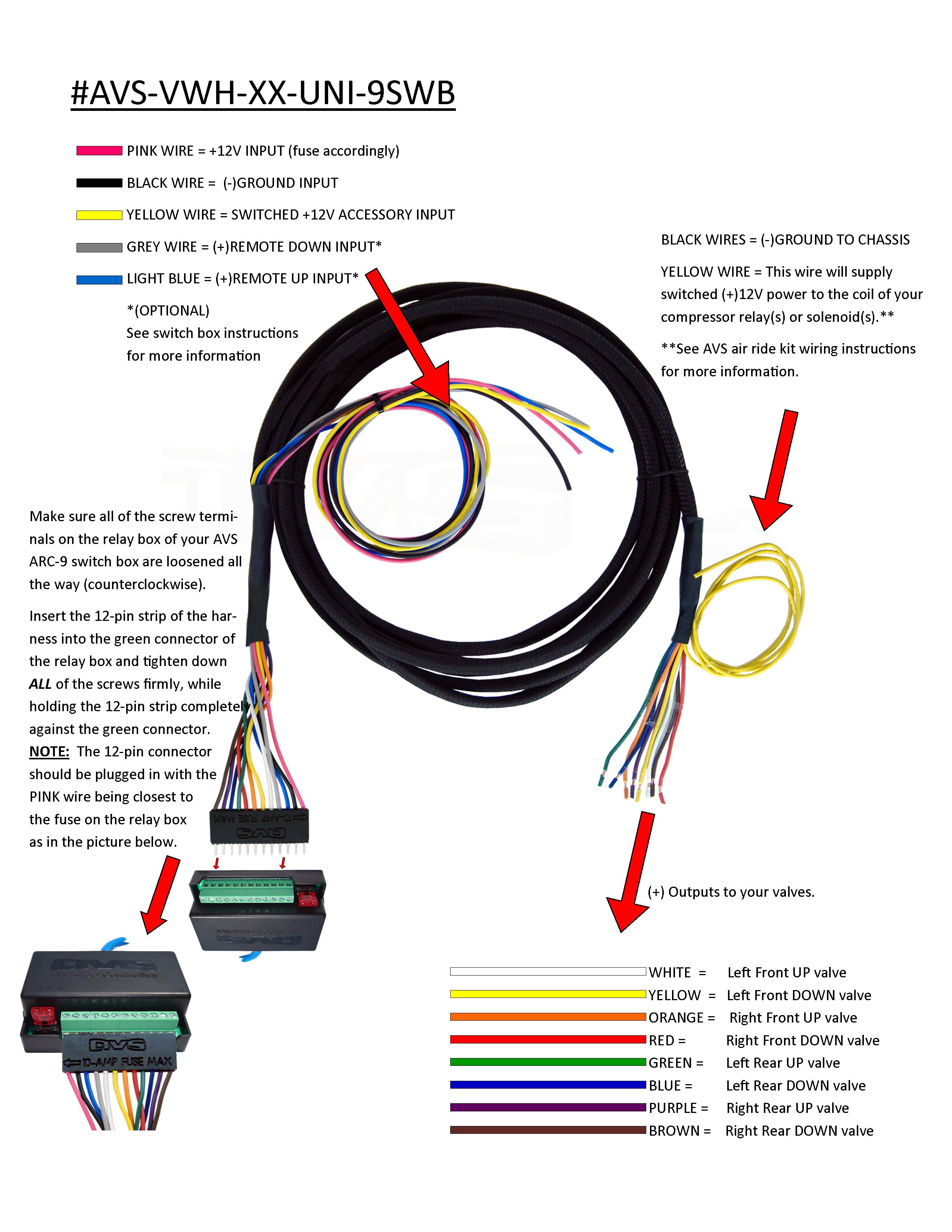
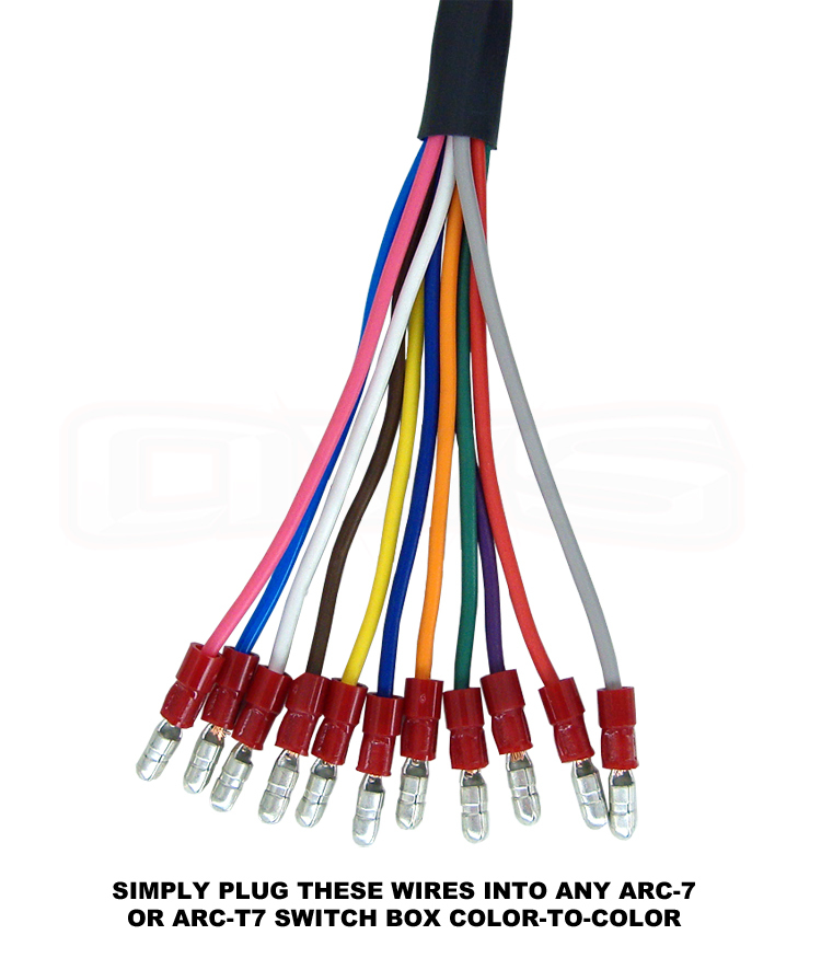
Also includes accessory wire to provide switched power to your compressors relayssolenoids. Avs valve wiring harness 10 15 20 accuair vu4 valve to avs 7 switch box avs brand plug and go wiring harness. 2 transfer hole pattern from the vu4 mounting template on page 22. Remote fill and dump wires for your avs. 4 place the ground eyelet from the vu4 wiring harness under one of the cap screws and make sure that this screw has good contact to chassis ground. Plugs directly into any avs 7 or avs arc t7 switch box and accuairs vu4 manifold valve.
Avs brand plug n play wiring harness. Also includes accessory wire to provide switched power to your compressors relaysolenoids. Plugs directly into any avs arc 7 or avs arc t7 switchbox and accuairs vu4 manifold valve.
Gallery of Accuair Vu4 Wiring Diagram