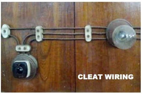
Installation of cleat wiring. The wires can be weather proof.

Cb 8399 Cleat Wiring It Is Vir Wire In Porcelain Cleat Free
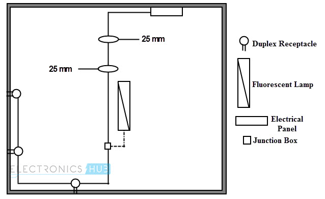
Cleat wiring diagram. It gives detailed information about wiring such that one can get an idea of making connection between the devices. The cleat wiring on insulators shall he installed in accordance to regulations. Work is first started from the ceiling rose or from the lamp bracket at the farthest point of the load circuit. It is permitted on systems up to 440v or 600v. The spacing between wires drawn through the cleats depends upon 1 line voltage and 2 type of circuit. Simple wire laying is done in this scheme of wiring.
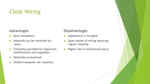
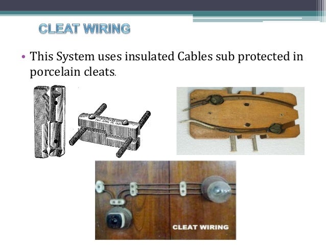
In cleat wiring vir pvc and weather proof sheathed cables are commonly used. Customization can be easily done in this wiring system eg. Cleat wiring system installation is easy and simple. The cleat has a two parts. Inspection is easy and simple. Electrical wiring system is classified into five categories.
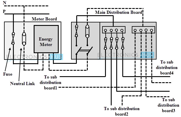
What is electrical wiringelectrical wiring is the electrical power distribution through the wires in a perfect manner for economic use of wiring conductors inside a room or building with better load control. What is type of circuit will be clear from table no. The electrical wiring diagram is a pictorial representation of the circuit which shows the wiring between the parts or elements or equipments. Disadvantages of cleat wiring. It is the oldest wiring method. Cleat wiring cant be use for permanent use because sag may be occur after sometime of the usage.
Porcelain cleats or plastic cleats two or three grooves screws. Procedure of cleat wiring in this wiring vir or pvc insulated wires are braided and compounded on walls or ceiling with the help of porcelain cleats. Spacing between wires in cleat wiring. Cleat wiring casing wiring batten wiring conduit wiring concealed wiring. The insulators are made by porcelain plastic or hard wood. Appearance is not so good.
Gallery of Cleat Wiring Diagram