If you have an rv style plug the wiring colors are as follows. Rv and commercial 7 wire plugs.

7 Pin Wiring Guide Wiring Diagram G11
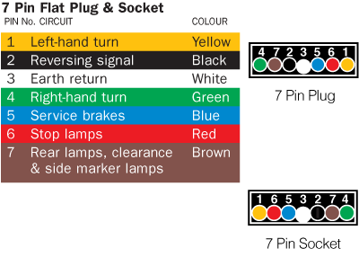
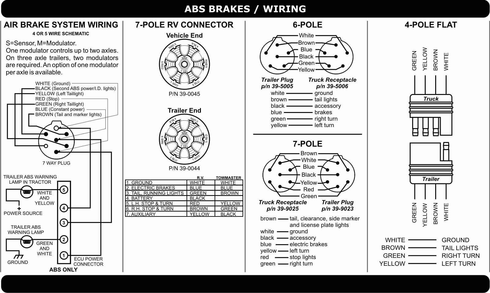
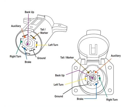
7 pin plug wiring diagram. This wiring diagram for 7 pin trailer plug model is more appropriate for sophisticated trailers and rvs. A wiring diagram is a type of schematic which utilizes abstract pictorial signs to show all the affiliations of parts in a system. It can transfer electricity better compared to the connector is suggested for higher level electric in the vehicle. 7 way plug wiring diagram standard wiring post purpose wire color tm park light green battery feed black rt right turnbrake light brown lt left turnbrake light red s trailer electric brakes blue gd ground white a accessory yellow this is the most common standard wiring scheme for rv plugs and the one used by major auto manufacturers today. If youre installing a 7 wire plug for an rv or a commercial vehicle the color of the wires included will be slightly different than that of the traditional 7 wire plug. Sometimes the cables will cross.
Were happy to help guide our customers to the right trailer or snow plow for them. Click on the image below to enlarge it. Wiring diagrams are comprised of 2 points. Wiring diagram for 6 wire trailer plug fresh 7 pin round trailer exactly whats wiring diagram. Constant 12 volt black. And we offer so much more than that.
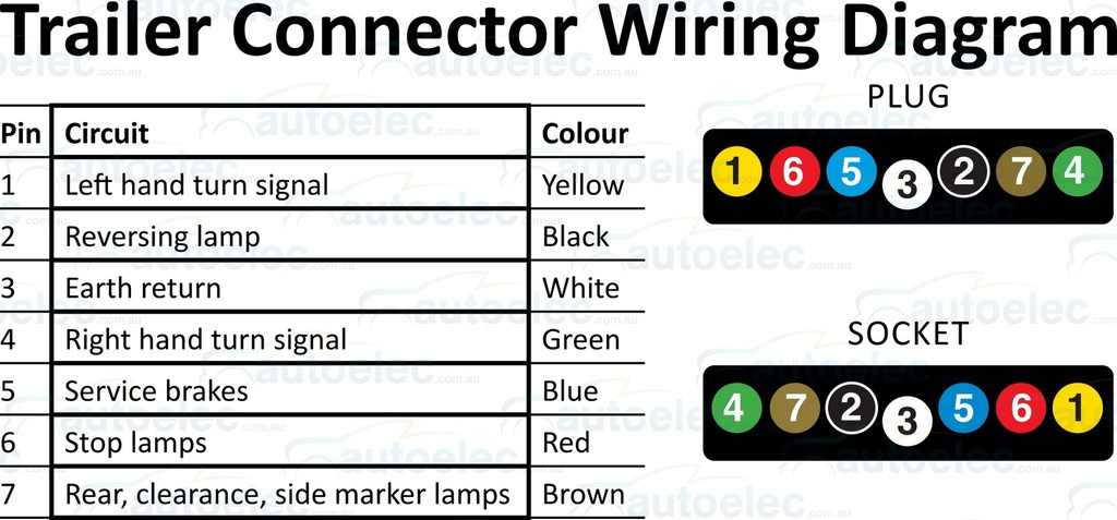
A colour coded trailer plug wiring guide to help you require your plugs and sockets. Collection of ford 7 pin trailer wiring diagram. A wiring diagram is a streamlined traditional photographic depiction of an electrical circuit. Includes guides for 7 pin 6pin 5 pin 12 pin 13 pin pin and heavy duty round plugs and sockets. Here are two wiring diagrams for the 7 pin n type trailer electrical plug. Reverse lights yellow.
Stop into our harrisburg pa dealership today or call to learn more. White pin to your ground. But it doesnt mean link between the cables. As stated earlier the lines in a 7 pin trailer wiring diagram with brakes signifies wires. Trailer wiring diagrams trailer wiring connectors. Signs that represent the components in the circuit as well as lines that.
There will be primary lines which are represented by l1 l2 l3 and so on. The first diagram is a simple set up of two brake lights two indicators and two side lights. Tail and running lights green. The second diagram shows two brake lights two indicators two side lights and a fog light. Various connectors are available from four to seven pins that allow for the transfer of power for the lighting as well as auxiliary functions such as an electric trailer brake controller backup lights or a 12v power supply for a winch or interior trailer lights. Here is the diagram for 7 pin connector.
Injunction of two wires is usually indicated by black dot on the junction of 2 lines. It reveals the components of the circuit as simplified forms as well as the power and also signal links in between the gadgets.
Gallery of 7 Pin Plug Wiring Diagram