Disconnect vehicle battery recommended. While school bus operations are paused get ready for the new normal.
Zonar Systems 81010 81010 User Manual
Zonar v3 wiring diagram. The new sanitation configuration is an extension of zonar evir which is already widely used for verifying fmcsas mandated pre and post trip inspections. Refer to your specific vehicle manufacturer guidelines for the installation of electrical components and wiring. If due to the particular. Prep your fleet for the restart. Find the gpsid sn number on the back of the unit. V3 gps unit v4 gps unit.
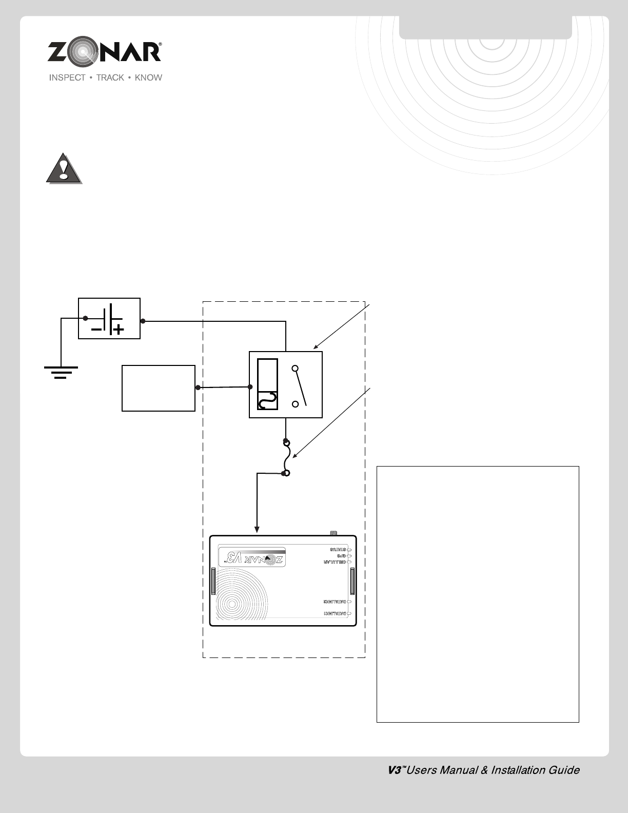
Please contact the vehicle manufacturer for any specific electrical questions gap created by improper use of probe proper use of probe 12 wiring guidelines wiring guidelines for unterminated power and ground leads 4 pin and moac t the authorized method for power termination on the zonar v3 system is the use of add a circuit fuse taps. Remove the fuse panel cover to gain access to the fuse panel. Refer to your specific vehicle manufacturer guidelines for the installation of electrical components and wiring. Details on operating the v4 and its built in applications and software are given in this guide. A professional team of zonar support technicians and engineers are available to answer your installation questions. With pto and five io expansion ports capture additional data from your assets like when the boom is raised door swings and plow drops.
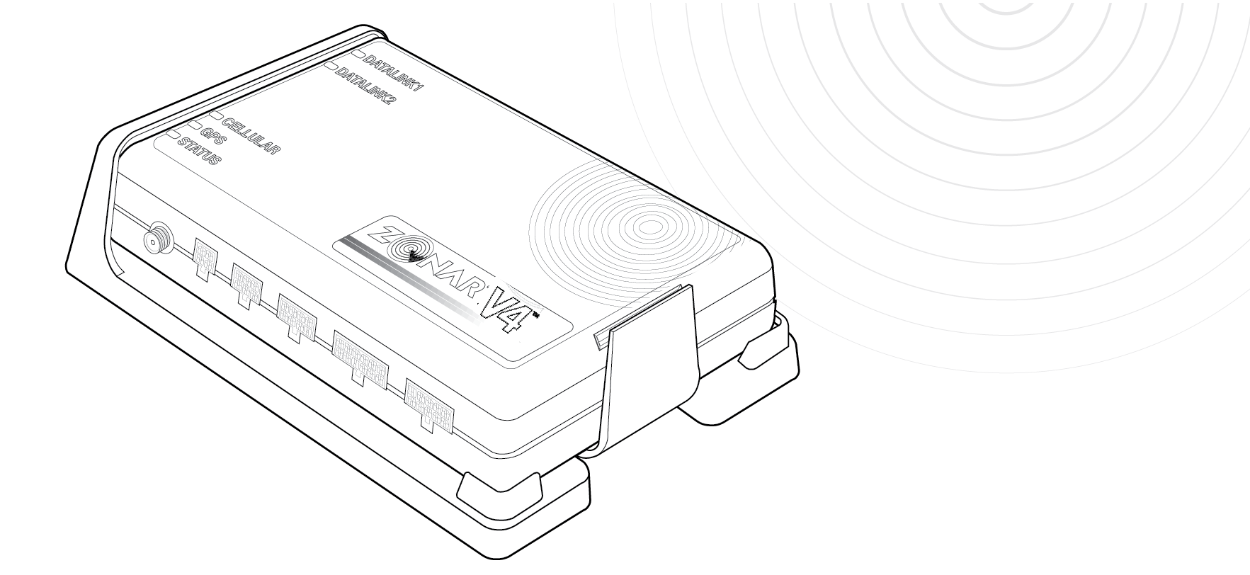
Flexibly designed zonar v4 is a unique telematics control unit that can be installed in your light duty heavy duty and off highway vehicles. A professional team of zonar support technicians and engineers are available to answer your installation questions. Plug in the connect powerdata cable to the gps unit the connect dock vehicle power and back up camera if desired. Connect requires a zonar gps unit to operate. Follow the diagram to the left to correctly connect the tablet cable to the gps unit. Whenever possible use fuse taps for power termination.
Refer to the cable guide for reference. Zonar recommends attaching an add a fuse or spade connector to the constant power wire. Zonars install manual says to put the unit on the dash but that looks to the existing gps antennae then location of the v3 doesnt matter as itwe also provide images such as wiring diagrams engine diagrams parts diagrams transmission diagrams replacement parts electrical diagrams repair manuals engine schemes wiring harness fuse. Disconnect gps unit 4 pin power. Take this time to prepare your fleet to resume usual. Wiring guidelines wiring guidelines for unterminated power and ground leads 4 pin and moac t the authorized method for power termination on the zonar v3 system is the use of add a circuit fuse taps.
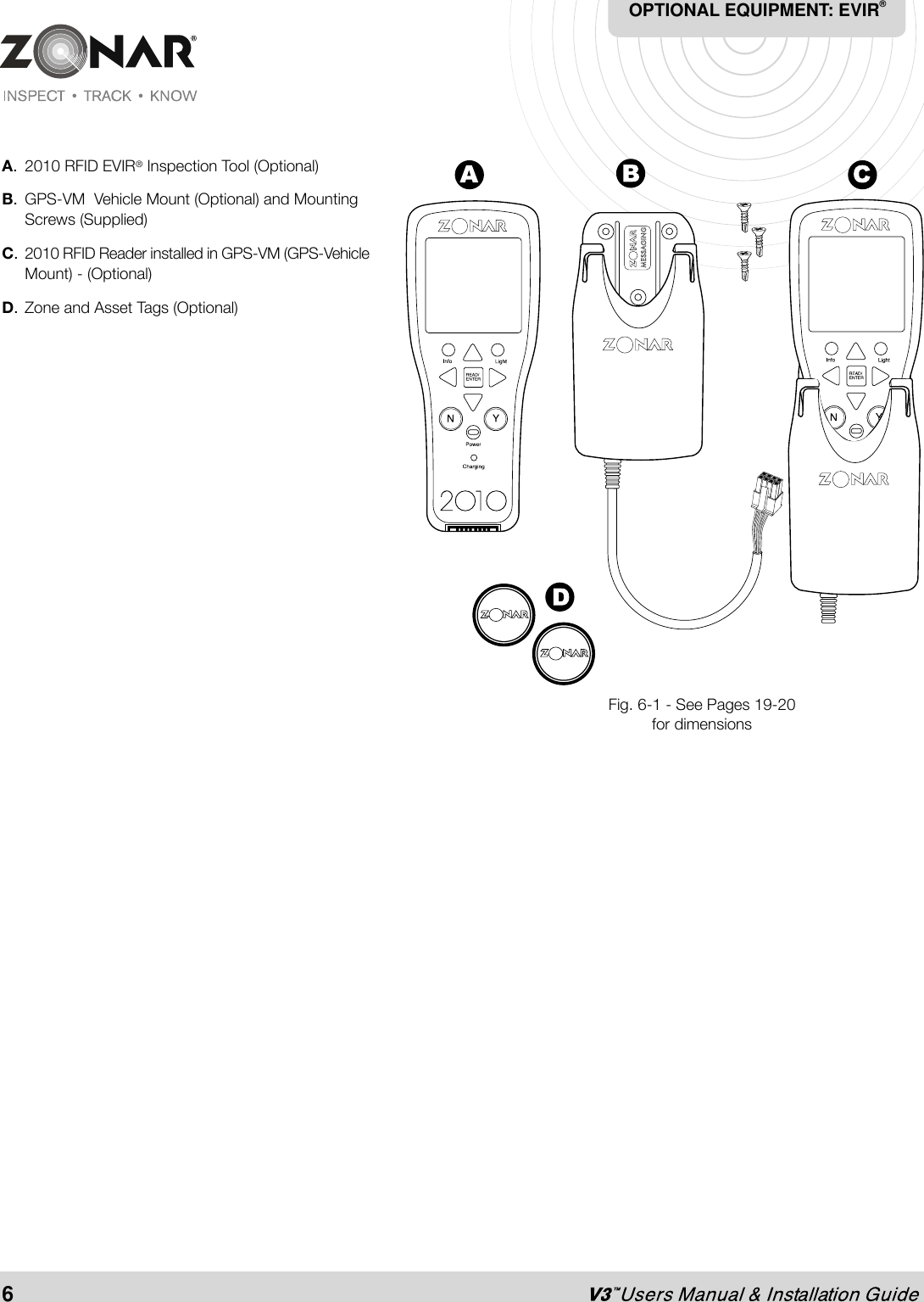
Locate a constant power source that measures 8 30 volts with engine off or on. The installation technician must record which gps unit is being installed in each vehicle before any zonar equipment is installed. V3r equipment 2010 reader part 20001. The constant power and ground wiring can most easily be connected through the fuse panel.
Gallery of Zonar V3 Wiring Diagram