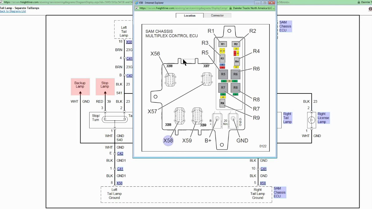
How to use this diagram system ÿ use the diagram to locate where on the chassis the connections will be located. The side of the connector shown is looking into the pins.
Acm Wiring Diagram Ghg14 Amc Wiring Diagram Dd15
Dd15 acm wiring diagram. Verify that the correct mcm cpc andor acm parameter list has been installed then clear the fault codes. The wiring for the vih 21pin to the mcm is listed in table 21pin connector to the mcm. Pin signal type function connector 1rpuh nc 2rpulnc 3pvim1nc 4 mvb5f electronic unit pump cyl 4 pin 2 5 mvb5 electronic unit pump common cyl. Leave a reply cancel reply. If faults become active go to step 3. If faults do not become active release the vehicle.
Ghg14 dd15 mcm wiring diagram. Epa10 dd15 cpc wiring diagram 371131 high idle regeneration aborted low exhaust temperature one thought on epa10 dd15 mcm wiring diagram lolita okerlund at. Have the aftertreatment control module acm motor control module mcm or common powertrain controller cpc been recently programmed. Your email address will not be published. Hardware and wiring mcm 120pin connector for mbe 4000 engines the pinouts for the 120pin connector for the mbe 4000 engine are listed in table 3 9table 3 10 table 3 11 and table 3 12. ÿ not all connections shown in the diagram will be on any one specific vehicle.
To order new harnesses for service or repair refer to parts bulletin 54 018. Some locations are approximate due to wheelbase differences. Dd15 troubleshooting powered by. The pinouts for the 120pin connector are listed in table mcm connector dd15 engine 1 of 4 table mcm connector.
Gallery of Dd15 Acm Wiring Diagram