Wiring diagram for module xps af safety relay. B the start button monitoring function is configurable depending on the wiring.

Telemecanique Type Xps Af Relay Switch
Xps af wiring diagram. Note there are no user serviceable components in the module. Emergency stop monitoring 1 channel wiring emergency stop monitoring 2 channel wiring safety level can reach silcl 3 conforming to eniec 62061 can reach pl ecategory 4 conforming to eniso 13849 1 safety reliability data pfhd 462e 9 1h conforming to eniec 62061 mttfd 243 years conforming to eniso 13849 1 dc 99 conforming to eniso. Xpsac module with an esc. Wiring diagram for module xps af safety relay. Le module ne contient pas de composants soumis à maintenance par lutilisateur. Wiring diagrams xpsav module with an emergency stop push button with 1 nc.
650 588 9200 outside local area. Failure to follow these instructions can result in death or serious injury. Contact automatic start or unmonitored start 1 jumper for automatic start. For maximum protection of the outputs please refer to technical data. Page 17 courtesy of steven engineering inc 230 ryan way south san francisco ca 94080 6370 main office. For safety circuits according to en 60204 11992en418 safety devices must use.
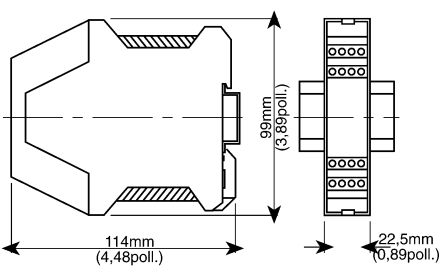
3 time delay opening safety outputs stop category 1. 2 instantaneous opening safety outputs stop category 0. Wire safety relay using wiring diagram shown in following wiring diagram. For the xpsaf it is the standard wiring diagram to use. Pour lautorisation dun circuit de sécurité selon. Xps af misure di ingombro dimensions maße identificazione dei morsetti terminal marking klemmenanzeiger 18 17111998.
Functional diagram for module xpsac. For maximum protection of the outputs please refer to technical data. Xpsaf5130 module xpsaf emergency stop 24 v ac dc. Esc external start conditions.
Gallery of Xps Af Wiring Diagram