The most effective gas detection systems often the xnx. Mon parts for ogs ovs ots ops 2 x xx pdf.
Honeywell Xnxutaennnnn Transmitters Honeywell Xnx
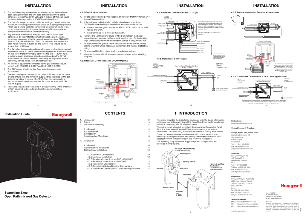
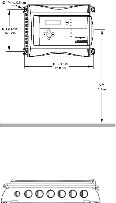
Xnx honeywell gas detector wiring diagram. See wiring diagram below. Honeywell analytics xnx universal gas detection transmitter safety manual. Xnx honeywell gas detector wiring diagram. It reveals the parts of the circuit as streamlined shapes and also the power and signal connections between the gadgets. Different gas detection applications on site. Click on the image to enlarge and then save it to your computer by right clicking on the image.
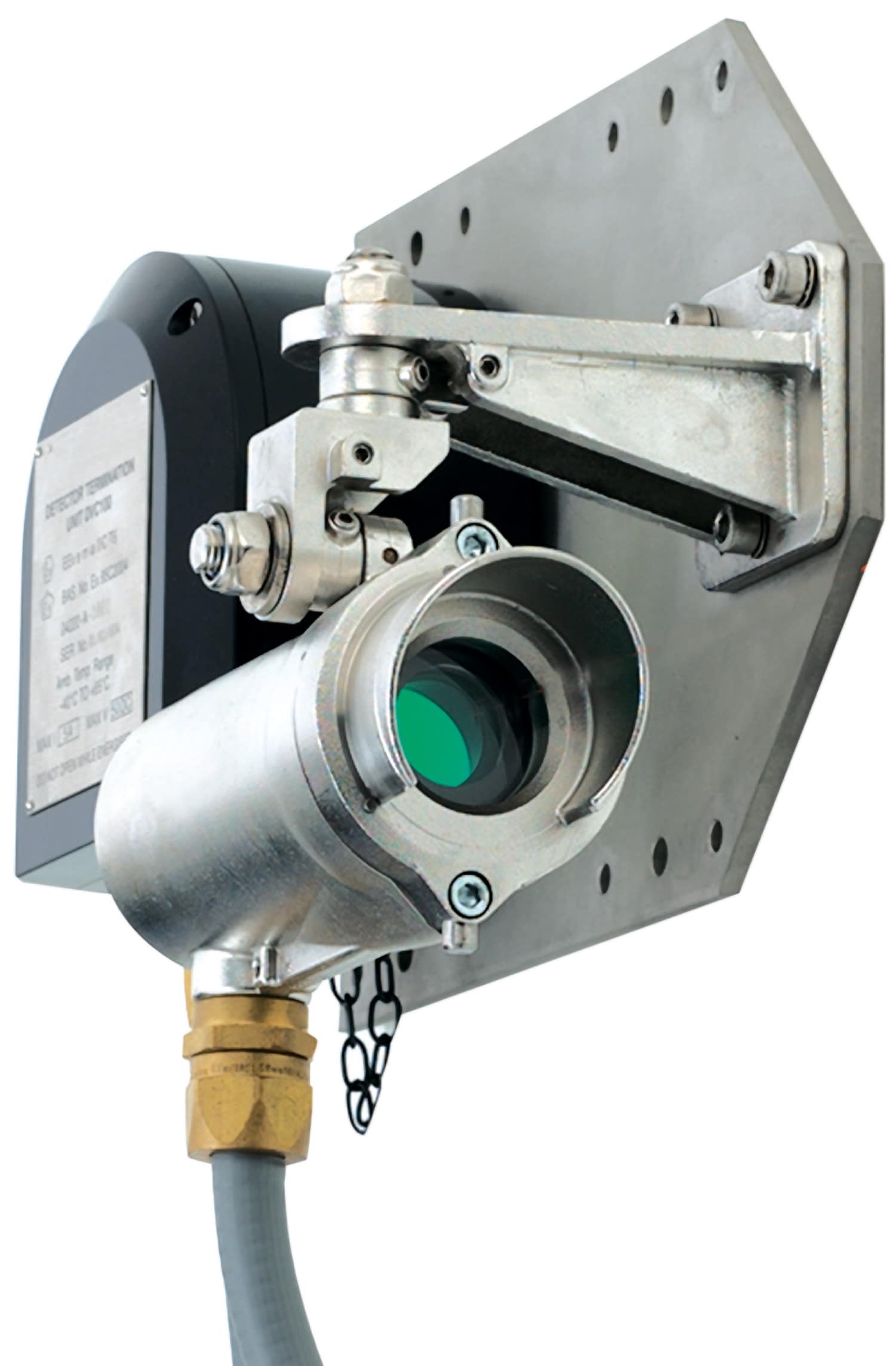
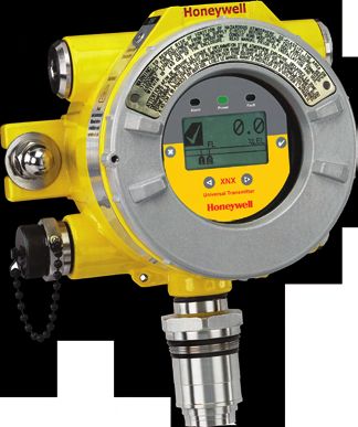
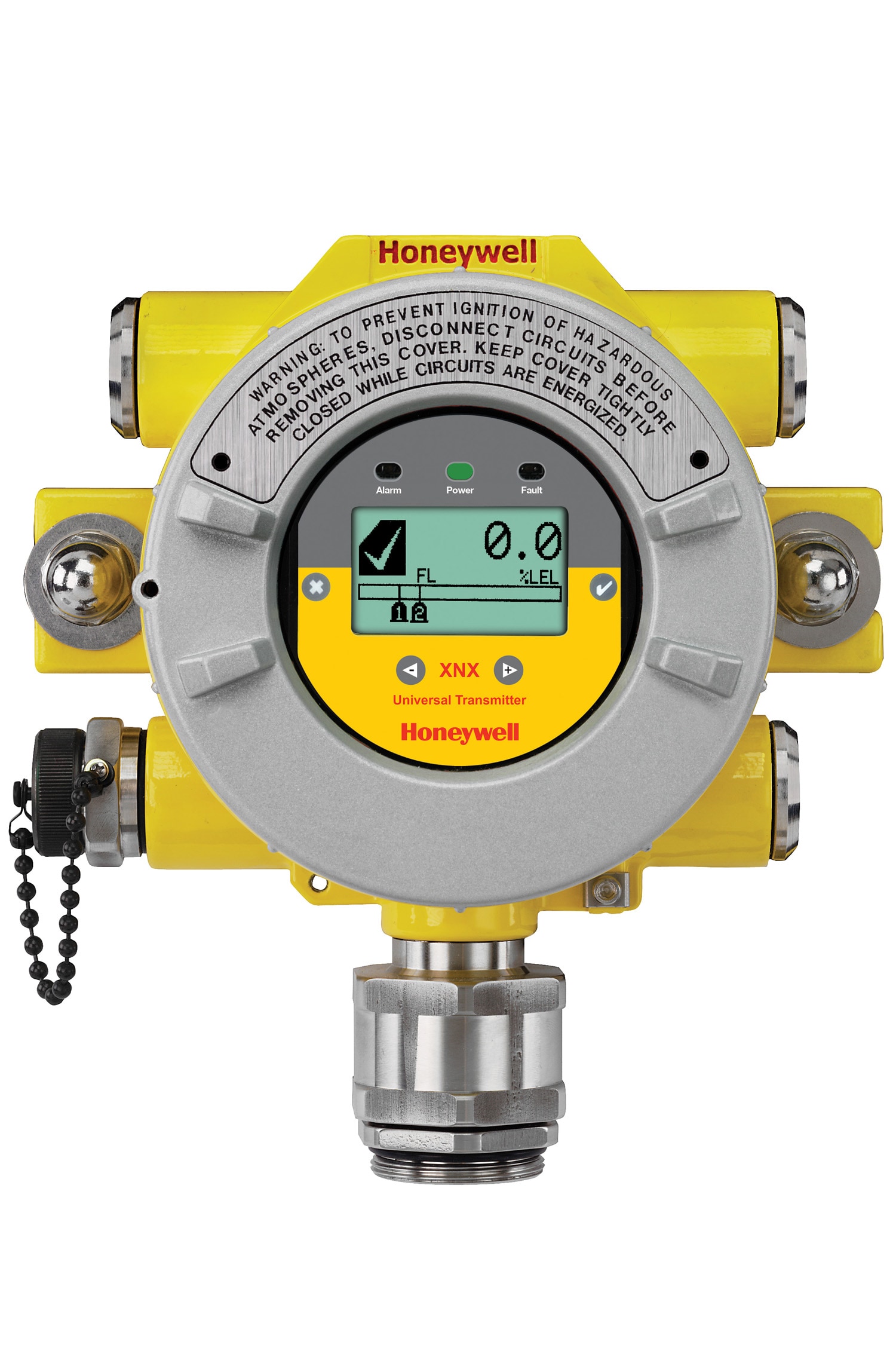
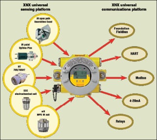
The most effective gas detection systems often employ a variety of detection technologies including point flammable detectors both catalytic and infrared type toxic and oxygen electrochemical cell type detectors and open path infrared detectors. Ec sensor interface to the xnx transmitter is intrinsically safe allowing the. Variety of xnx honeywell gas detector wiring diagram. Settings the xnx universal transmitter is a comprehensive gas detection. Honeywell xnx transmitter for gas detection supports catalytic bead kb. Wiring schematicsxnx is an extremely flexible transmitter that can be configured to accept an input from any of the honeywell analytics range of gas sensor technologies.
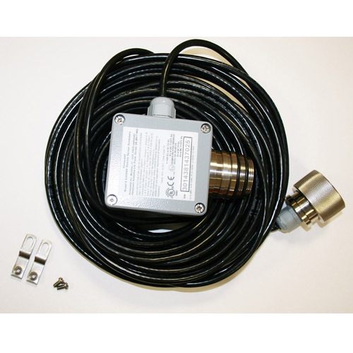
Honeywell analytics recommends that an 8 service length of wiring be maintained. Collection of xnx honeywell gas detector wiring diagram. 2 2 4 ma output common connections and power. When wiring the xnx transmitter and the searchpoint optima plus for remote applications the maximum distance between the xnx transmitter and optima plus is 100 feet 33 meters using 075 mm2 18 awg wire minimum. A wiring diagram is a simplified conventional photographic representation of an electrical circuit.
Gallery of Xnx Honeywell Gas Detector Wiring Diagram