Diagnosis and repair of western snowplow electrical systems. Ultramount mvp plus diagrams.

Western Unimount Diy Controller Part 1
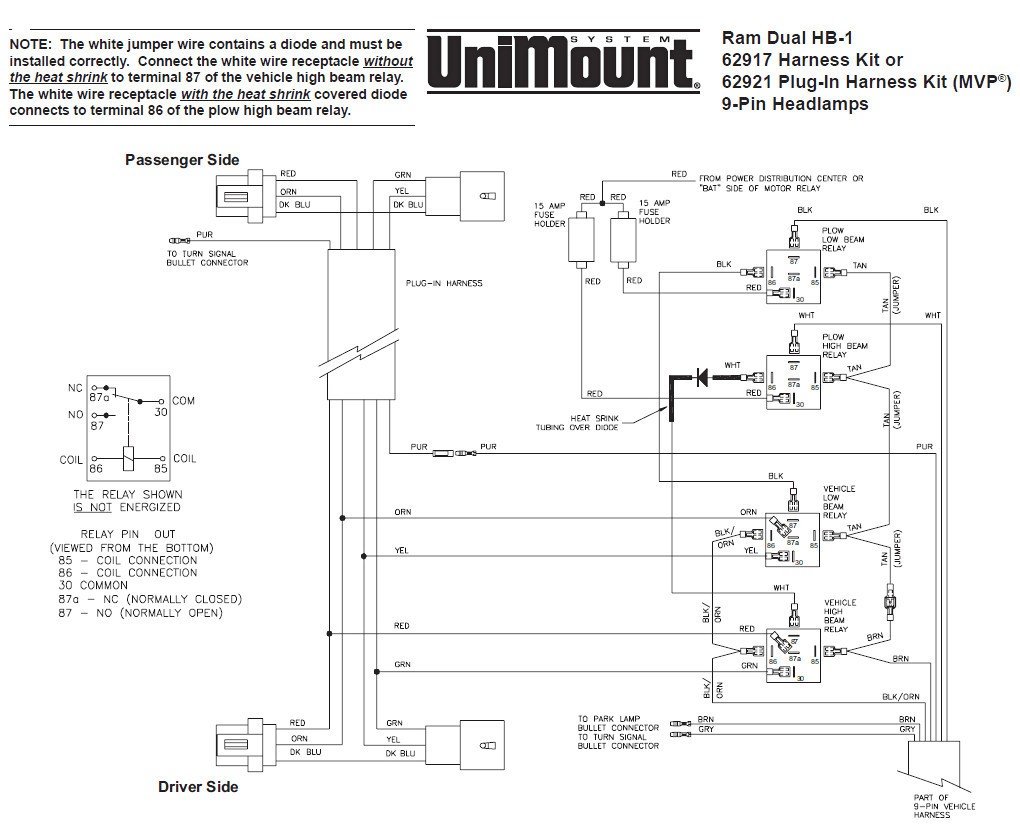
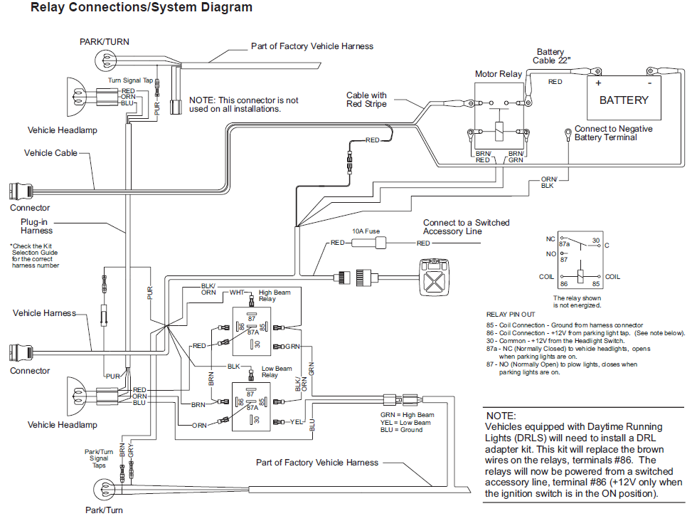
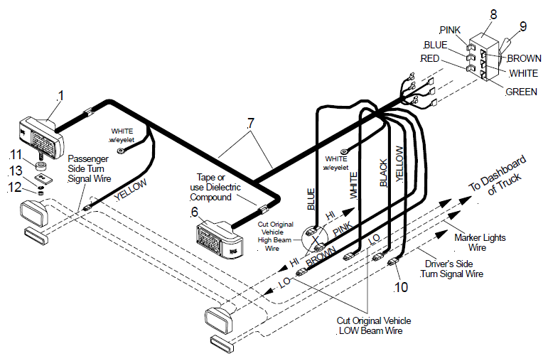
Western mvp plow wiring diagram. Box 245038 milwaukee wi 53224 9538 form no. A wiring diagram is a simplified standard pictorial representation of an electrical circuit. A division of douglas. 21857 june 15 2003 preface. It shows the parts of the circuit as simplified forms as well as the power and also signal links between the tools. To resume raising the plow release the button and press again.
After reaching the desired height release the button. The selection list has specific vehicle and snowplow requirements. 13639 may 24 1999 caution see your western outlet for application recommendations. A wiring diagram normally provides details about the family member placement and plan of devices and terminals on the tools to assist in structure or servicing the device. It contains schematics diagrams and charts which supply information for the various types of vehicle and plow headlamp systems. Plow will automatically stop raising after 25 seconds.
61540 61550 66640 western products po. 62526 62921 63398 headlamp kit no. Although intended primarily as a diagnostic tool for headlamp systems the hydraulic system circuitry is also included to show the complete electrical system. Plow diagrams blade t frame lift frame. Assortment of western snow plow wiring diagram. Plug in harness for mvp without drls.
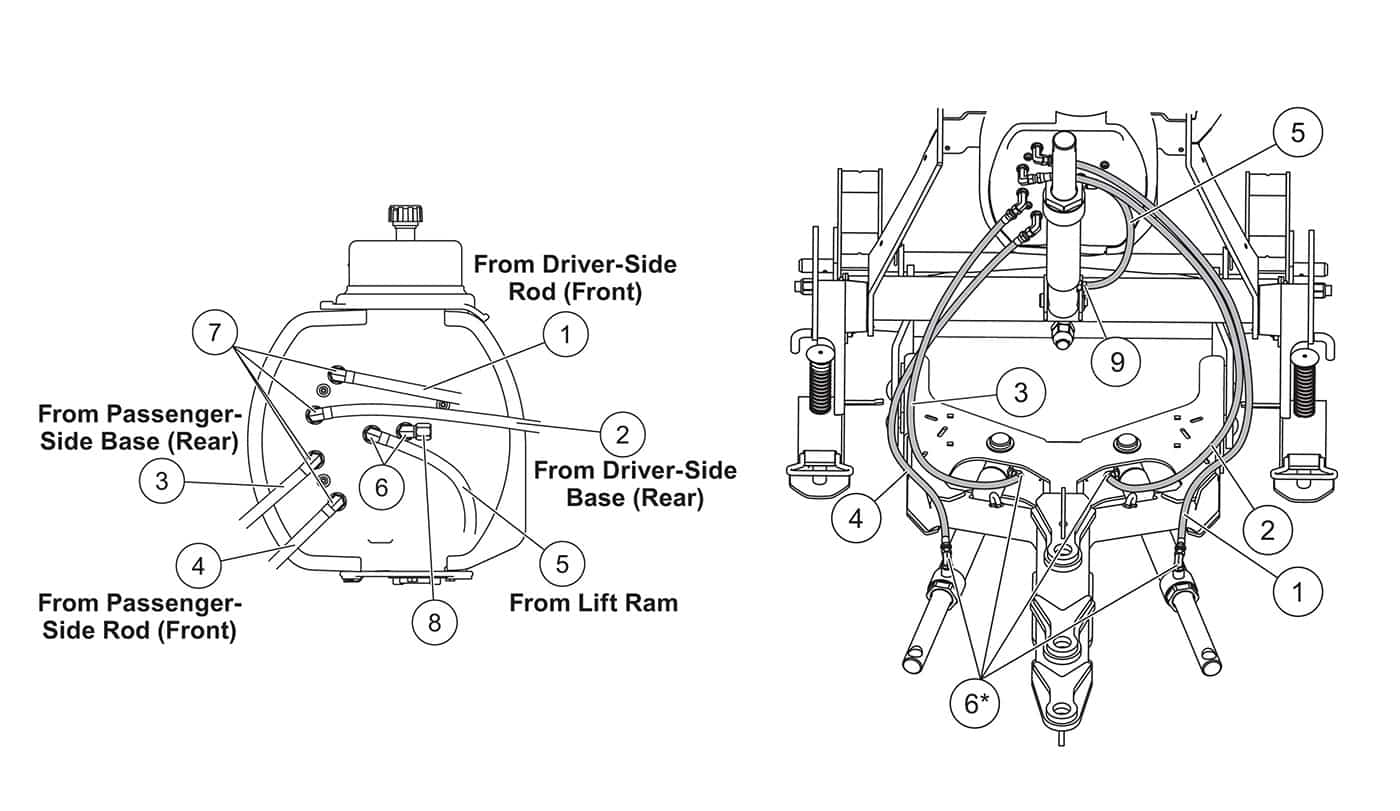
Mvpultramount w 3 plugs hydraulics electrical system controls. Servicing the western mvp snowplow. Electrical diagrams isolation module controllers plow side electrical 2 plug isolation module nighthawk headlamps. Lower press this button to lower the plow. Mvp flostat parts diagram. Hydraulic diagrams hydraulic unit hoses lift ram angle ram.
Parts diagrampdf installation instructionspdf mvp plus ultramount w 2 plugs fleetflex hydraulics electrical system controls. Parts diagrampdf installation instructionspdf mvp plus ultramount 2 w 2 plugs fleetflex hydraulics electrical.
Gallery of Western Mvp Plow Wiring Diagram