Vector control block diagram torque producing current iq perpendicular to the motor flux vector. Dc drives weg cfw11 user manual.

Top 10 Largest Mini Circuit Breaker Ideas And Get Free
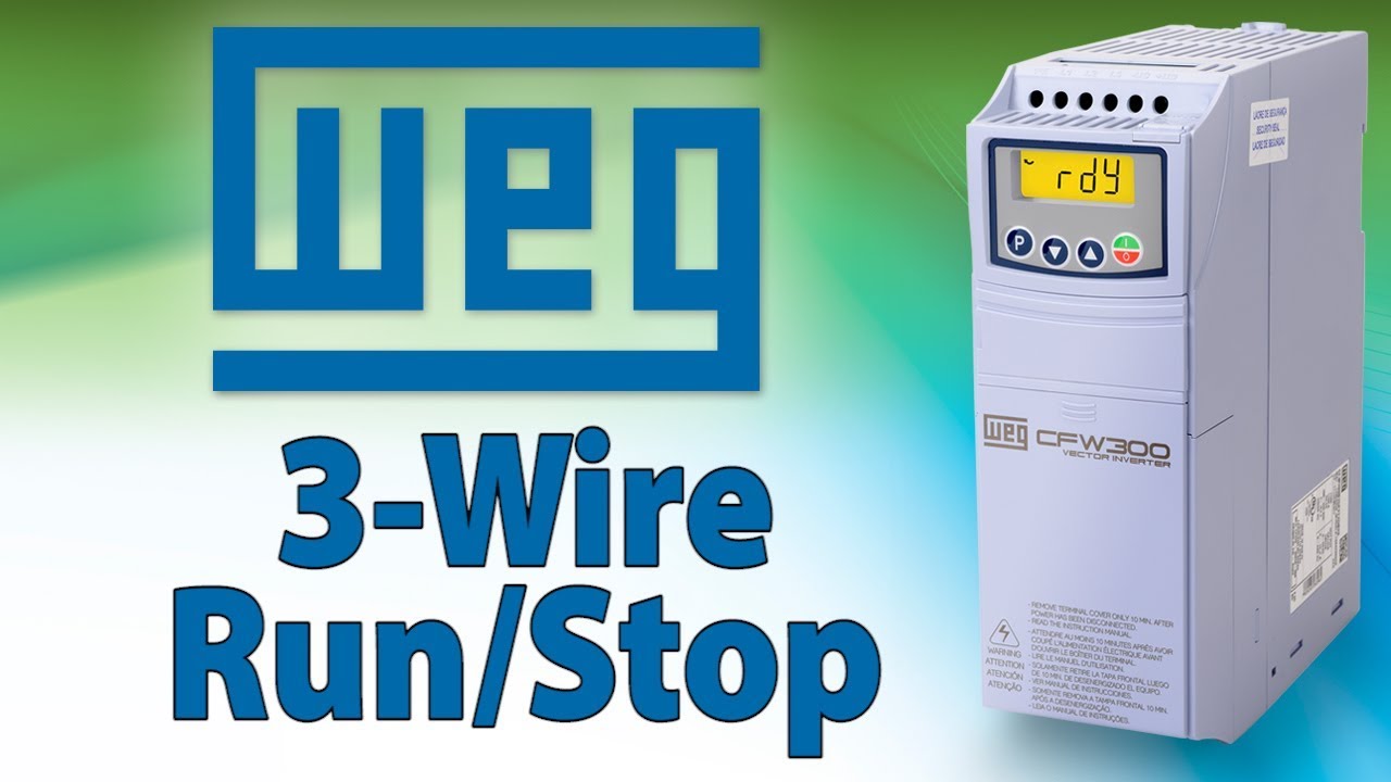
Weg cfw11 control wiring diagram. Examples of wiring diagrams of inverter control signal figure 328 a and b inverter control wiring examples xc1 and xc25 terminals to realize sto or ss0 ie stop category 0 and ss1 stop category 1. Scalar control vf vvw or vector control programmable in the same product. Execute the oriented. Revision performed by summary date 00 andre vd linde new document june 2015. Dc drives weg cfw11 user manual. English spanish brazilian portuguese.
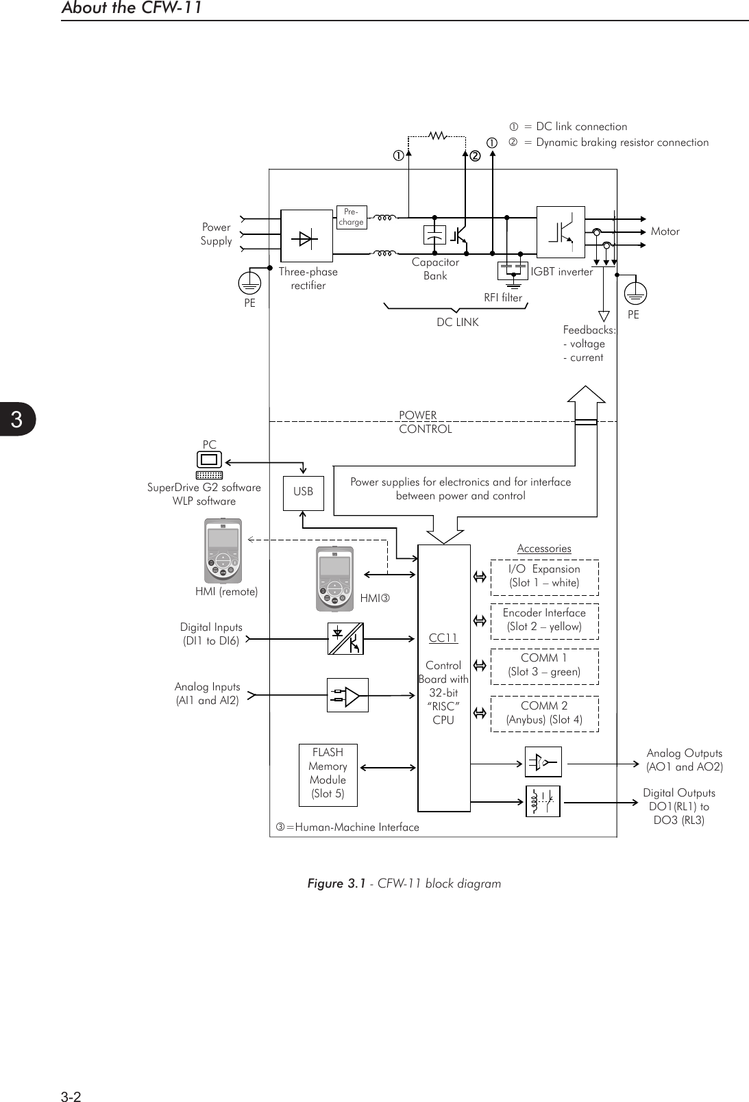
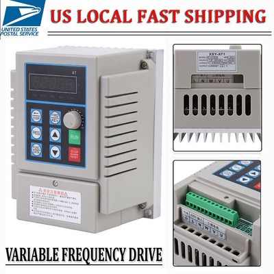
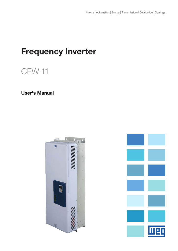
Operation of the cfw11 frequency inverter using the ethercat protocol 37 pages. According to the chapter 3 installation and connection of the cfw 11 user manual wiring all the power and control connections. Aimed at increasing customers productivity the cfw11 offers the following innovations. The cfw11 is a variable speed drive intended for use with asynchronous motors. D adjust the inverter to operate with the application line and motor. Mounting options standard features.
The cfw 11 frequency inverter is a high performance product designed for speed and torque control of three phase induction motors. Vfd 3 wire vfd control with forward and reverse tutorial weg cfw300 variable frequency drive duration. The main characteristic of this product is the vectrue technology which has the following advantages. A 47 cfw11 cfw11 variable frequency drives wegs cfw11 uses state of the art technology to control motors up to 600hp. According to the section 53 of this manual. 08995620 05 software version.
Cfw11 kmf 01 and kmg 01 extractable mounting kit for size f and g date. Page 94 adjust the password p00005.
Gallery of Weg Cfw11 Control Wiring Diagram