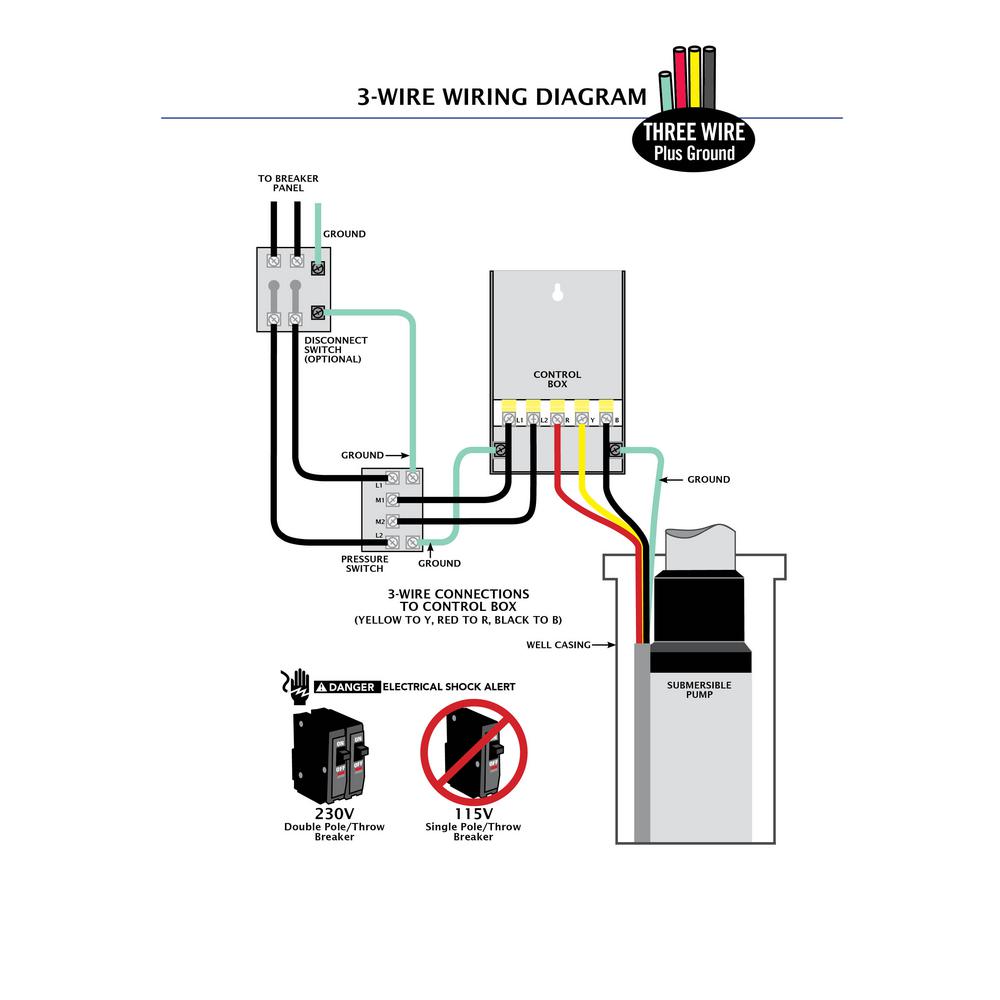
A wiring diagram is a simplified standard pictorial depiction of an electrical circuit. Why we called a single phase submersible motor a 3 wire submersible that we also know that we have two wire in single phase power supply.
Eco Flo 1 Hp Control Box For 4 In Well Pump
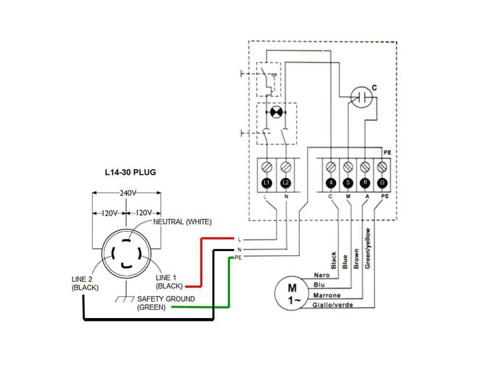
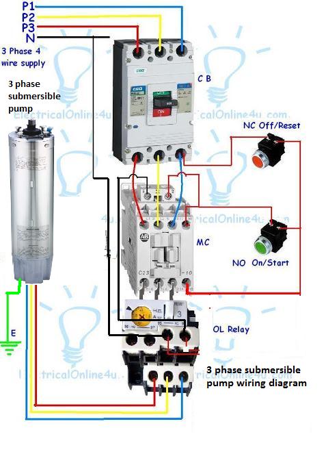
Water pump wiring diagram single phase. Attach one wire that is going to the pump to the screw head terminal that sets just next to the power wire. Motor maintenance single phase motors and controls page 53 menu. The diagrams for both the two and three wire pumps can be downloaded using adobe. In the above one phase motor wiring i first connect a 2 pole circuit breaker and after that i connect the supply to motor starter and then i do cont actor coil wiring with normally close push button switch and normally open push button switch and in last i do connection between capacitor. Wiring a motor for 230 volts is the same as wiring for 220 or 240 volts. Assortment of single phase submersible pump starter wiring diagram.
Adjoining cable routes might be shown roughly where specific receptacles or fixtures must get on a typical circuit. 12 1 hp crc qd relay 282 40 5015 sixth digit depends on hp. It reveals the elements of the circuit as streamlined forms and also the power and signal links in between the gadgets. After determining the voltage is zero disconnect the motor wires directly from the pressure switch box m1 and m2. Single phase submersible pump starter wiring diagram building wiring representations reveal the approximate locations as well as affiliations of receptacles lighting as well as irreversible electric solutions in a building. Today i am hear to write about submersible pump control box wiring diagram in this post you will complete understood about 3 wire submersible pump wiring diagram which is an single phase submersible pump motor.
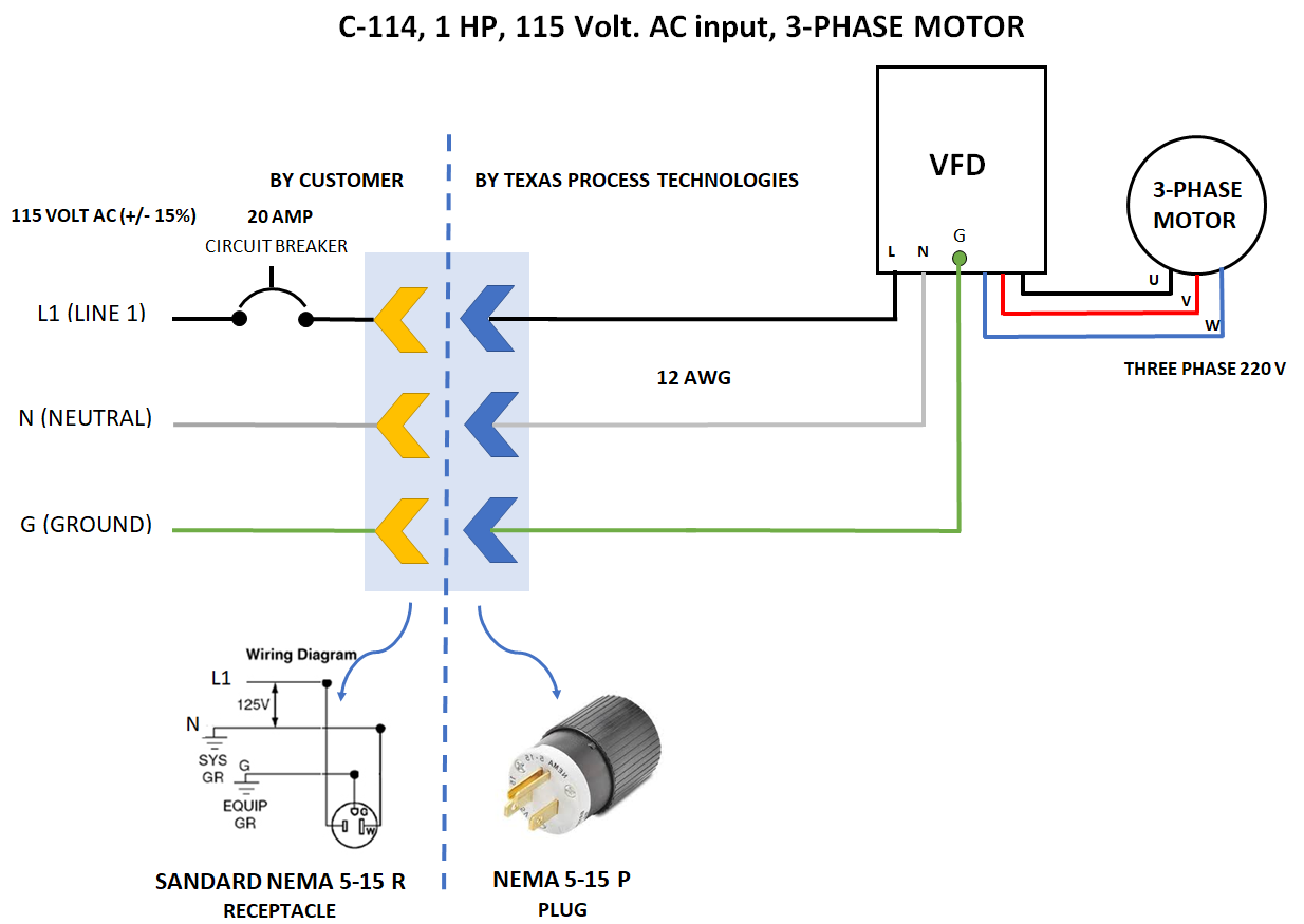
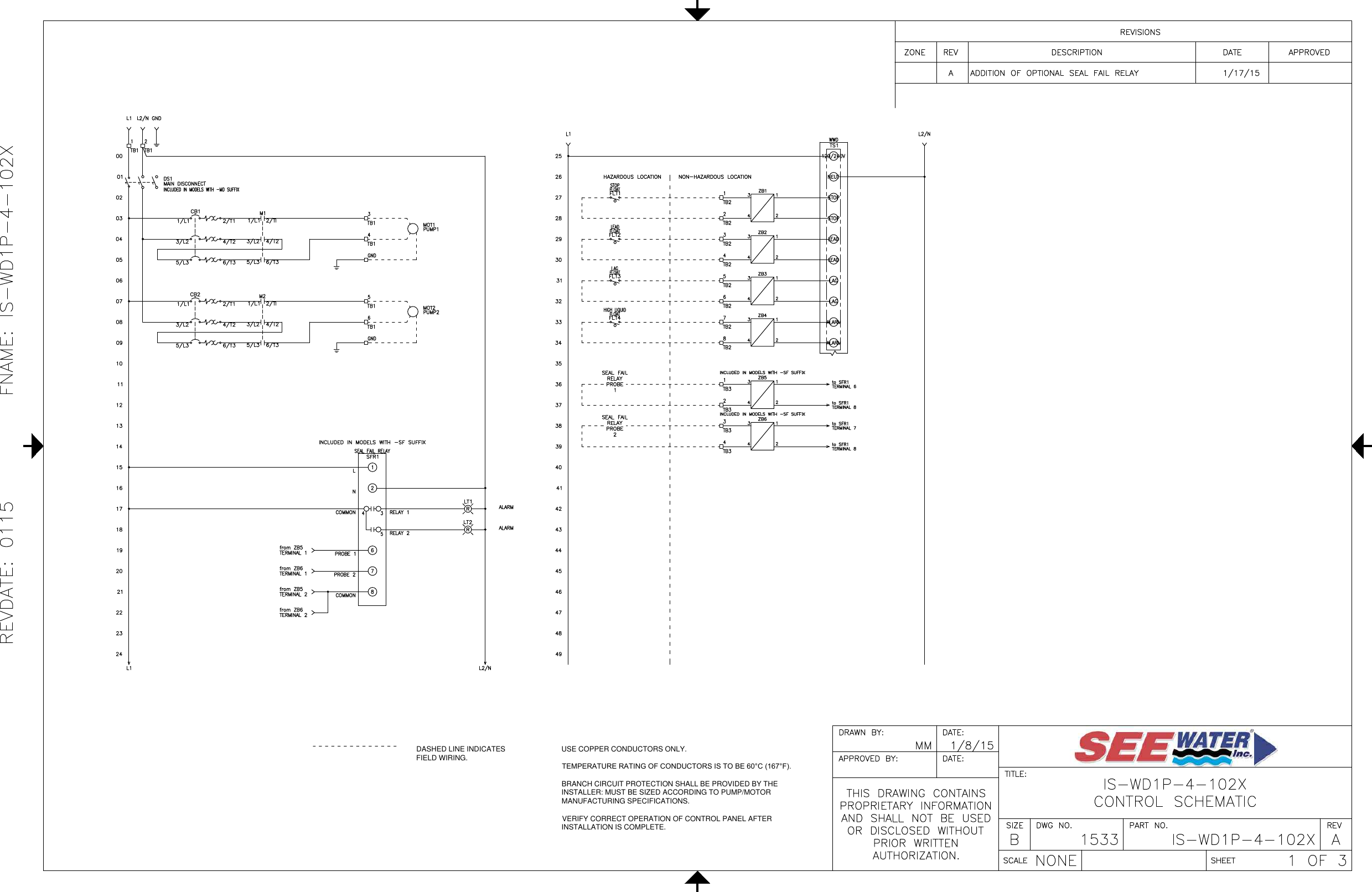
This will act like a single switch. Terminate the other set of contacts in the same manner. Residential power is usually in the form of 110 to 120 volts or 220 to 240 volts. With the last power wire going to the second set of contact screw heads and the last pump wire going to the last screw head terminal. Single phase wiring diagrams single phase wiring diagram for 05hp pumps with governor switch single phase wiring diagram with governor switch single phase wiring diagram without governor switch three phase wiring diagrams three phase 208v wiring diagram three phase 230v wiring diagram three phase 460v wiring diagram three phase 575v wiring diagram kb pump wiring diagrams kb pump 230v wiring. Page 54 control box wiring diagrams.
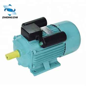
The above diagram is a complete method of single phase motor wiring with circuit breaker and contactor. Single phase motors are used to power everything from fans to shop tools to air conditioners. 13 1 hp qd relay 280 10 4915 sixth digit depends on hp. The green ground wire should also be terminated to the box and a ground coming from the panel. To replace the two wire pump. I hope after watching the above single phase submersible pump starter wiring diagram guide video tutorial i hope now you will fully understood the complete submersible pump control starter wiring diagram or installation and now you will be able to wire or make your own submersible pump motor starter however now if you have any question regarding the video tutorial or diagram then you can ask.
Pump selection find the right pump for your job latest products view our latest products. A wiring diagram usually gives information regarding the family member setting and arrangement of devices as well as terminals on the devices to assist in building or servicing the device.
Gallery of Water Pump Wiring Diagram Single Phase