Vista 32fb designed to integrate seamlessly with cctv access control and a full range of fire and burglary components honeywells ademco vista 32fb provides the ultimate protection of life and property. Vista 32fb summary of connections j4 keypad port 2 see instr.

Honeywell Ademco Vista 48a Installation And Setup Manual Pdf
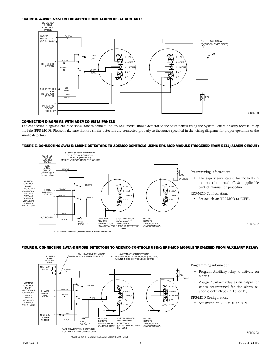
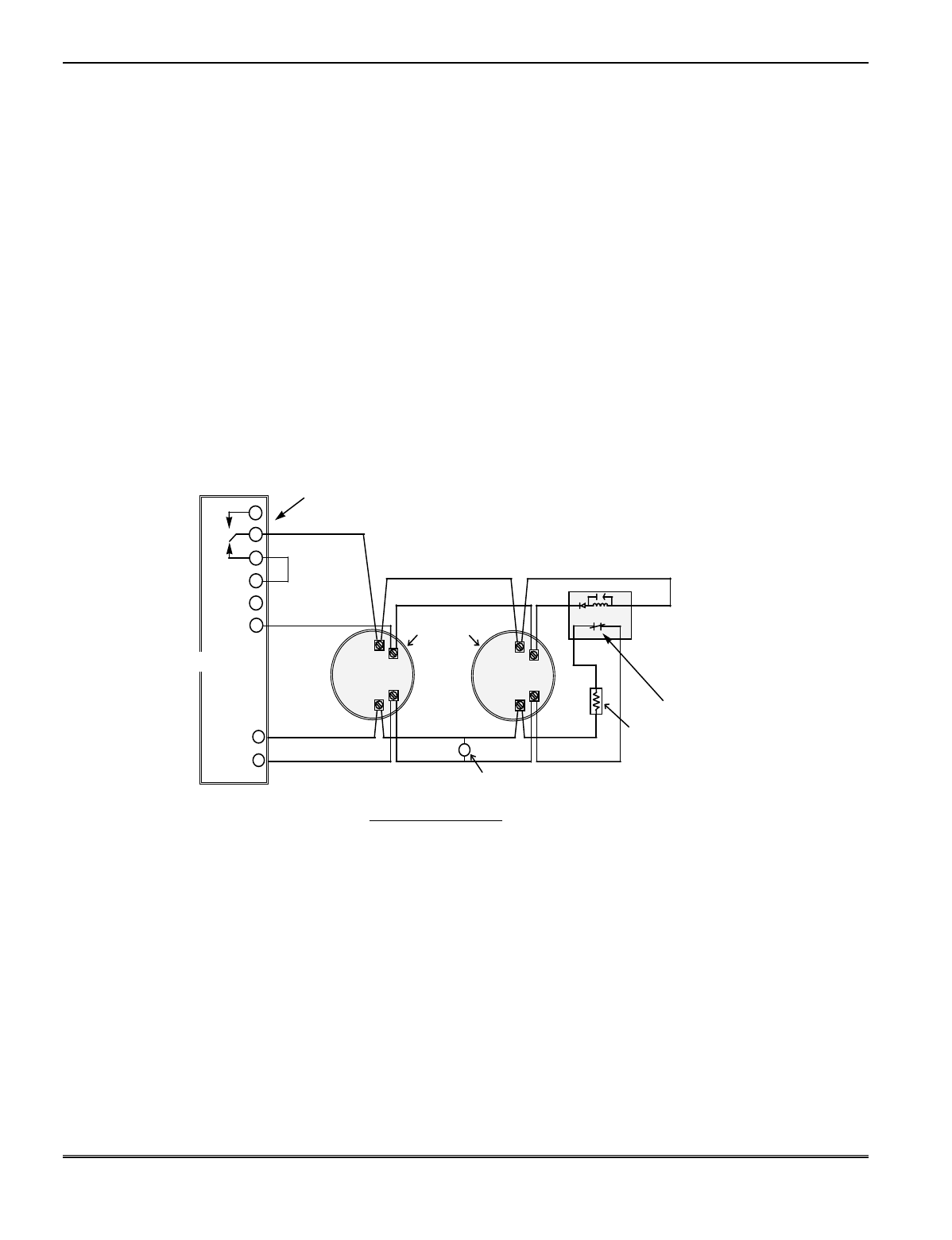
Vista 32fb wiring diagram. Wiring wire the vista 32fbpt as shown in figure 8 1 below. Control cf relays devices through the 70 manual relay. Page 42 vista 32fb installation and set up guide wiringaddressing rpm devices all devices on the polling loop must be wired in parallel to the and polling loop terminals of the control panel 28 and 29. Vista 32fb program wiring diagram. 13112018 13112018 5 comments on vista 32fb program wiring diagram. Aux pwr 2 to keypad red wire rating.
10 14 vdc 400ma max. Sending vista 32fbpt system troubles to the fire alarm panel. Data in 2 to keypad green wire 5. The vista 32fbpt has not been evaluated for use as a slave communicator in ul installations. You can wire from device to device or have multiple branches connected directly to the control panel in a star configuration as. The vista 32fb control panel provides features that allow the system to meet ul864 commercial fire requirements.
Closing time using temporary schedules or by programming special user schedules. Ground to keypad black wire 4. Data out 2 to keypad yellow wire w6 blue interface to 5140dlm main dialer on hook voltage threshold intact. To meet these requirements follow the guidelines outlined in this section. The ul listed commercial fire and burglary control platform can control up to two separate partitions independently and supports up to. Programming field settings for ul compliance.
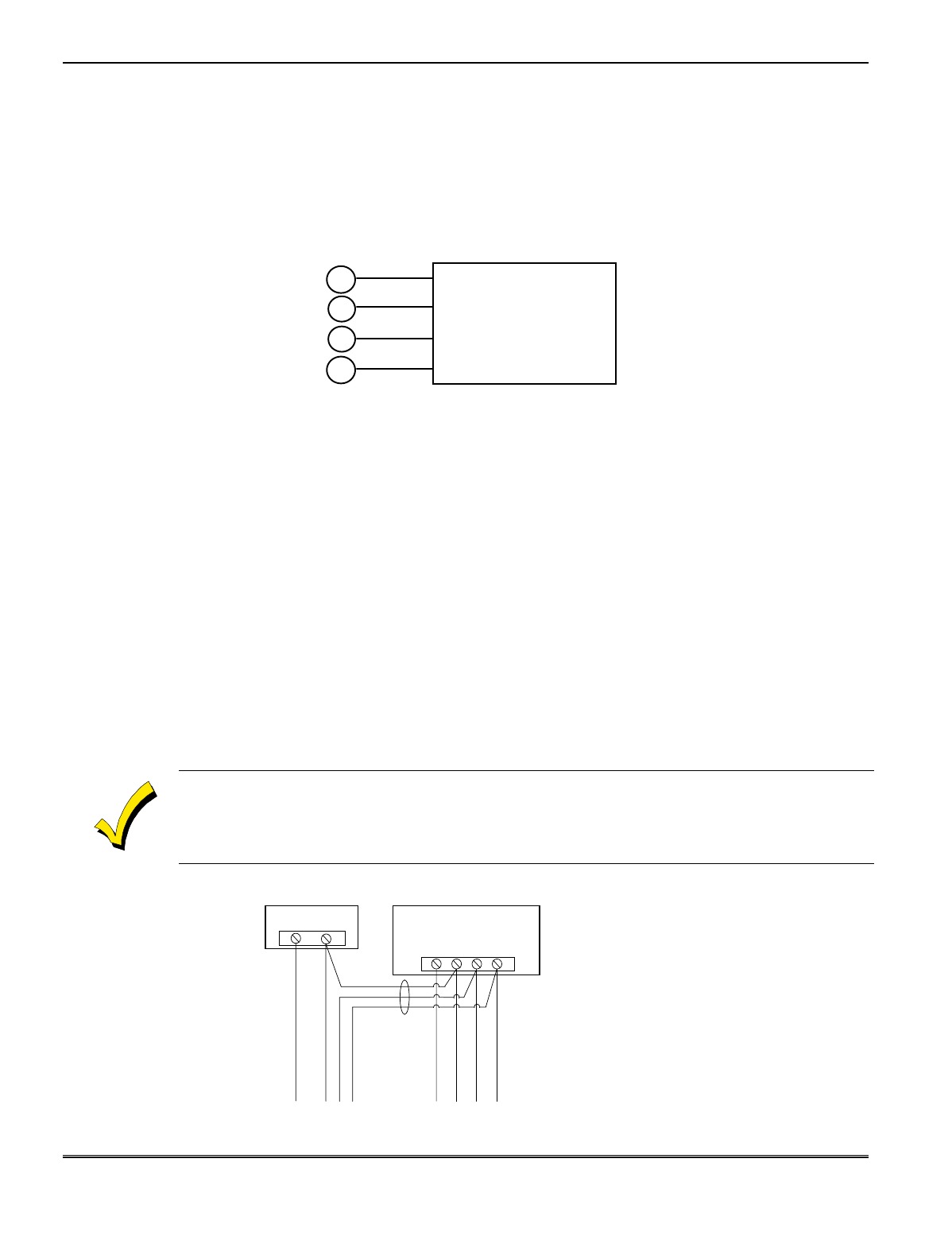
Regarding port 2 use 1. Be sure to tag the wires at the terminal box to identify their connections between the fire alarm panel and the vista 32fbpt. See note 1 7.
Gallery of Vista 32fb Wiring Diagram