From assembly or wiring diagram. They are universally adaptable.

Wt 3443 Vdo Rudder Angle Indicator Wiring Diagram Schematic
Vdo rudder angle indicator wiring diagram. Always disconnect battery ground before making any. This kit is sold separately sku 30108 mfg 440 050. Do not use tee angle or reducing adapters for temperature senders as the tip may not be immersed in the water flow. This project is quite simple and consists only of a gauge sending unit and interconnect wiring. What is needed then is a rudder indicator to aid in centering the rudders prior to shift steering. Includes a faria gauge at the helm and a vdo faria rudder position sending unit.
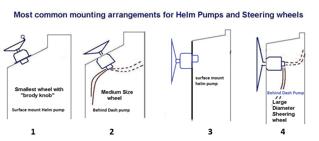
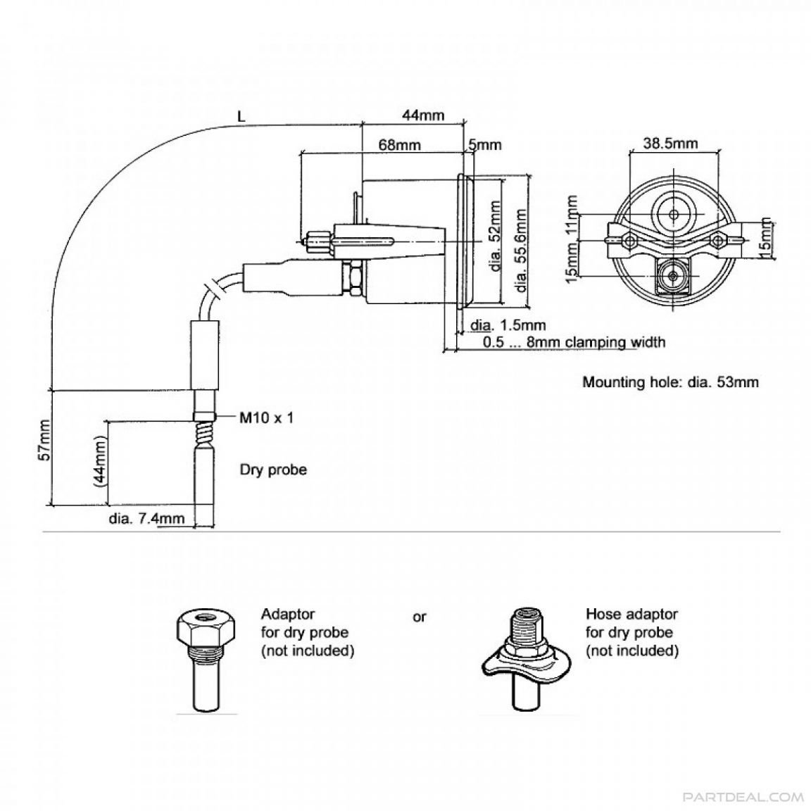
Rudder angle indicator 52mm 1224 volt. Mount the gauge and secure with the vdo spin lok clamp. See page 3 for mounting options and instructions wiring the gauge illustration a. Rudder angle indicator 52mm 1224v tech support 1 800 265 1818. Viewline 52mm wiring diagram 2014 viewline standard resistive gauges 52mm installation sheet 2014. Siemens vdo pitot pressure to speed pulse system 2004.
Instrument kit installation and wiring instructions siemens vdo. Temperature gauge pressure gauge rudder angel gauge trim gauge fuel gauge fresh water gauge for level type sensor tu00 0752 5207102 1 6 1 technische änderungen vorbehalten technical details subject to change tu00 0752 5207102 gb safety information the product was developed manufactured and inspected. Rudder angle indicator automobile electronics pdf manual download. The viewline depth indicator measures water depth. A rudder angle sender mounting kit is also available to connect the transmitter arm assembly to rudder cable. Viewline rudder angle gauge 85mm 2012 viewline rudder gauges 52mm 2008.
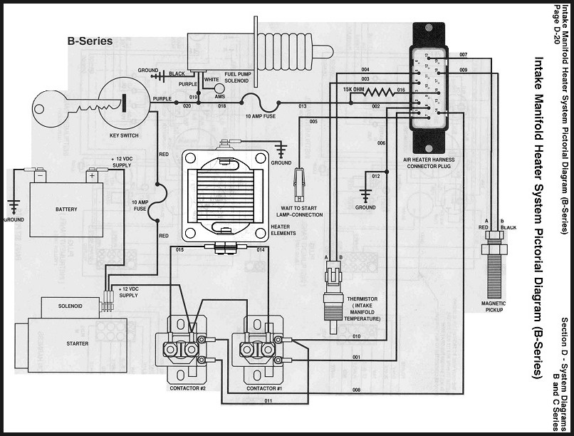
3 content content instrumentation6 tachometer 6 synchronizer 8 gps speed 9 depth gauges 10 temperature gauges 11 pressure gauges 15 rudder angle 20 fuel level gauges 21 trim 25 ammeter 26 voltmeter 27 fresh water and waste water 28 hour counter 31. It shows the components of the circuit as simplified shapes and the aptitude and signal connections in the middle of the devices. View and download vdo rudder angle indicator installation instructions manual online. Vdo rudder angle indicator wiring diagram wiring diagram is a simplified adequate pictorial representation of an electrical circuit. Vdo rudder angle indicator senders these senders are constructed of stainless materials to provide rudder position measurements or z enging. Do not use teflon tape on sender threads.
Route wires from the instrument to. On vdo rudder angle indicator wiring diagram. Description language type date size. Wiring diagram wiring of power and ground to each gauge illumination wiring and wiring of senders to each.
Gallery of Vdo Rudder Angle Indicator Wiring Diagram