Wiring diagrams and further information continues below. The problem is due to the combined cylinder stat and overheat stat.

Dd 3337 As Well Wiring Diagram Y Plan On Central Heating
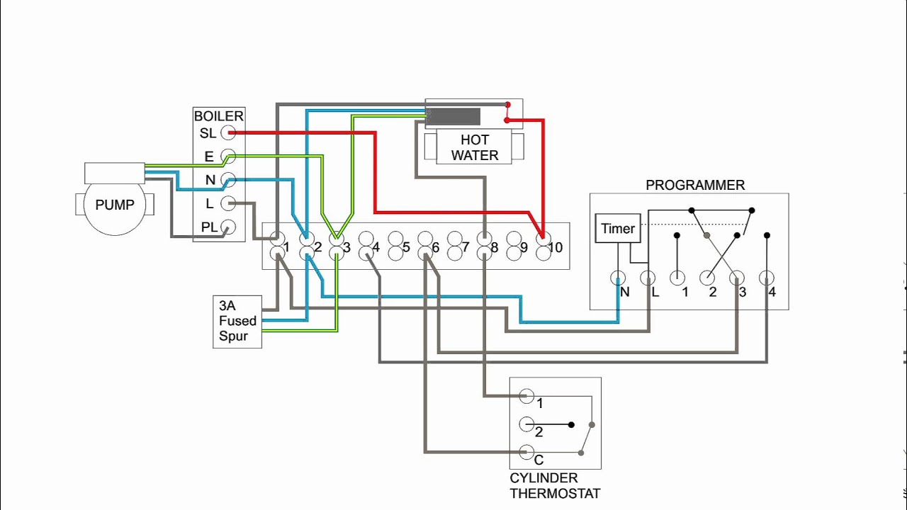
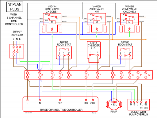
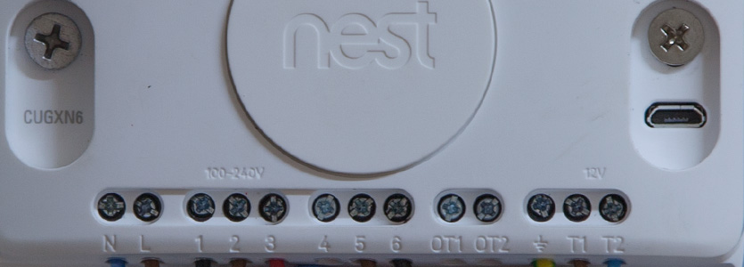
Unvented cylinder y plan wiring diagram. Output from the normal cylinder thermostat is connected to the high limit thermostat and the output from that powers the 2 port valve motor. In a y plan heating system you must have a wire connecting the hot water off terminal at the programmer usually terminal number 1 and the satisfied terminal on the cylinder thermostat. The unit has a stainless steel inner vessel which ensures an excellent standard of corrosion resistance. Though they do say that a y plan can be used with the safety zone valve. The problem is that telford only show a wiring diagram for an s plan in the installation manual. Orange grey wires from ch zone are not required please isolate opentherm make safe.
The cylinder is a purpose designed unvented water heater. Heating control ntc cylinder sensor connect timer to the no dhw demand nc no dhw e orange grey 2. Unfortunately the installer has not been able to work out how to wire it. All products are insulated. The outer casing is a combination of resilient thermoplastic mouldings and plastic coated corrosion proofed steel sheet. These terminals are joined together with the grey wire from the motorised valve.
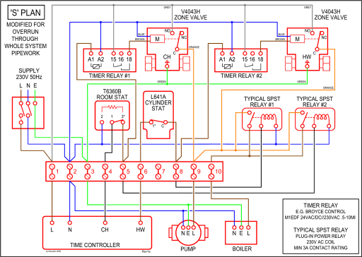
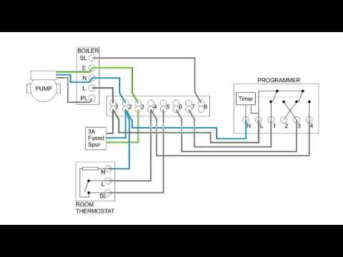
X range x plan wiring diagram unvented cylinder option gyellow cut off dhw sl coil. Wiring is based on the standard y plan with the addition of a high limit thermostat and a 2 port motorised valve. These are shown at the bottom right of the diagram. This video covers the wiring and electrical operation of a y plan system. This diagram shows the wiring layout using the most typical components. Here coloured wires indicate the permanent mains supply to the boiler and programmer.
Gallery of Unvented Cylinder Y Plan Wiring Diagram


/cdn.vox-cdn.com/uploads/chorus_asset/file/19752179/tankless_water_heater_promo.0.jpg)