Drive unit unidad de manejo unité dentraînement 2. Antenna masts coaxial cable and rotator cable figure 2 figure 3 2.
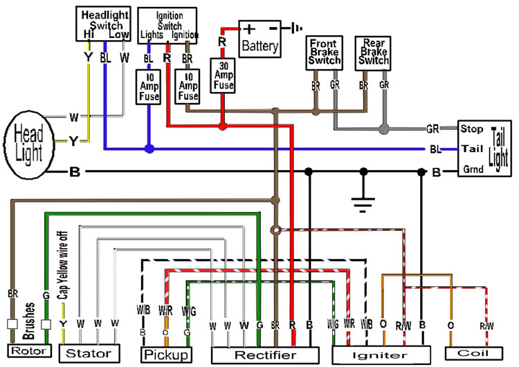
650wiringchoppertj8 Jpg
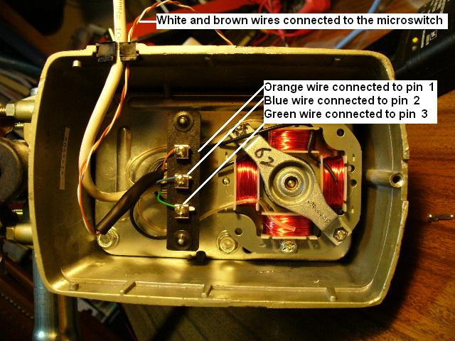
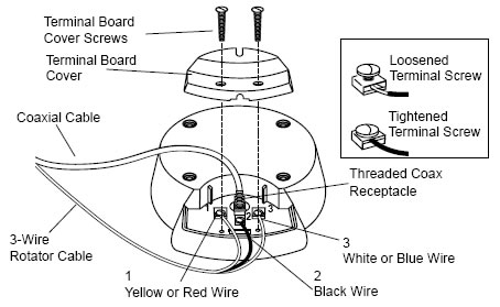
Tv antenna rotor wiring diagram. All channel master antenna rotors use 3 conductor rotor wire. A short coax cable is ran from the tv antenna output to the preamplifier input. Most rotor wire will be color coded. A rotor wire is then ran from the outside motor into the house to the control unit. It works by a synchronous motor in the control and the rotor. Remove the bottom or access plate of the drive unit housing and attach the rotor wires.
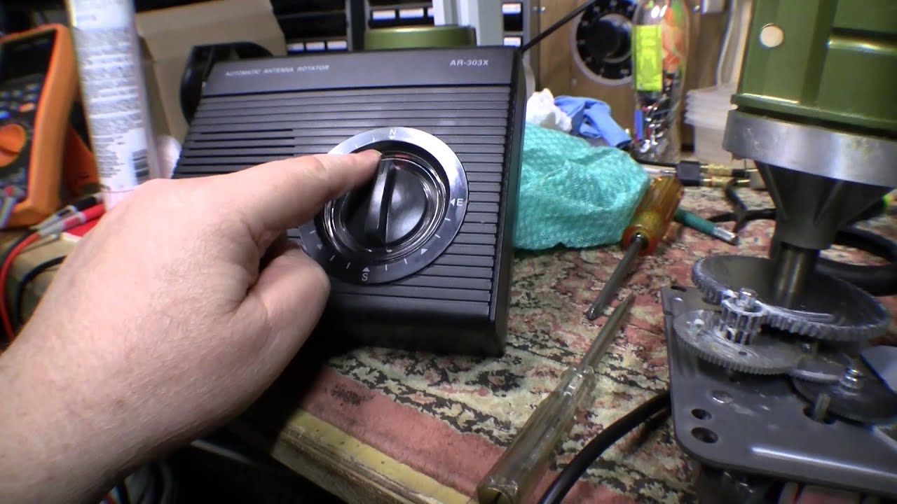
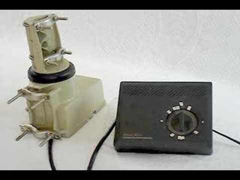
Thanks magnushowever this is an old unit with a dial you turn the dial the rotor turns the antennathe wires come into the house ffrom the antenna and then to the box which controls the rotorturn the dial which turns the antennathe wires are to this box. Antennas mounted indoors do not require a ground. There is no brake so wind can blow the antenna around and unsync the whole thing. The rotor can accommodate pipe of up to 2 outside diameter. Look in you instruction manual to see what wire size to use for longer runs. 15 complete routing of the antenna lead wire and rotor wire to the tv set per antenna manufacturers instruc tions.
The 4 foot cable is best for the hd stacker antenna. The rotor wire as shown. Remote control control remoto. Tv antenna preamplifier mount rotor cabling grounding and much more including tv antenna installation diagram. This location is usually near the main tv. The indicator assumes everything is in sync but it isnt always.
Control box installation s tep a. Stanoff antenna wire slack antenna lejowiae step 11 f ig. Our 25 foot cable works well for the ez hd antenna. They built the ham model hd 73 from 1978 through 1992 with a short break in 1990 due to production problems. Tv antenna installation guidelines for better tv reception. The radio shack roor has no feedback circuit.
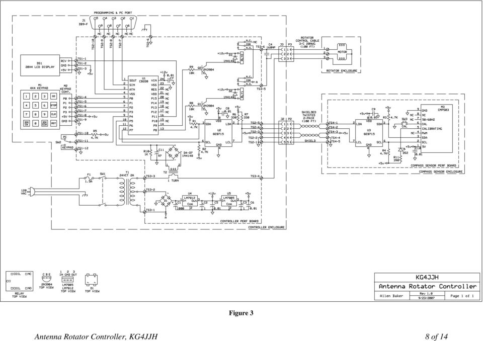
From the ground block run coax cable indoors to the preamplifier power injector. There are 3 separate color coded wires inside of the jacket of the rotor wire. Tv antenna rotor wiring diagram installation guidelines question motor voltage of old from alliance qrz forums wiringiagram ll channel master rotator 480618 at schematic 284971 sz 00 fb eps 1000 1 pictures img 4053 jpg diagramntenna rotorring random in servo nrs new and rebuilt rotors control boxes for sale 10241024 kanvamath org arduino. For runs up to 200ft you can use 22ga 3 conductor wire. Control unit rotator wire not included unidad de control el cable del rotor no está incluido unité de contrôle fil du rotor non inclus 3. The rotor control unit is located inside of the home at a location of your choice.
Continue to use separate stand offs for anten na wire and rotor wire. Tv antenna rotor wiring. The tenna rotor line was the standard tv antenna rotor for many years but the drop in demand for over the air ota local tv services forced them to stop production in 1990. Digital ota tv now offers more channels all with outstanding picture and sound quality. From the preamplifier output run coax cable to the ground block. The control really has no idea where the rotor is.
Gallery of Tv Antenna Rotor Wiring Diagram