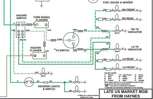
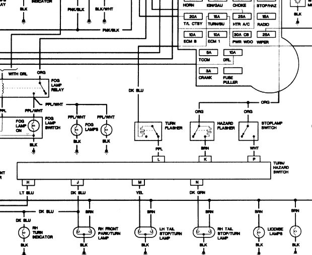
Flashers and hazards turn signal flasher wiring diagram. The flasher receives power from one of 2 fuses depending on whether or not the hazard switch is operated.

The Care And Feeding Of Ponies Turn Signals
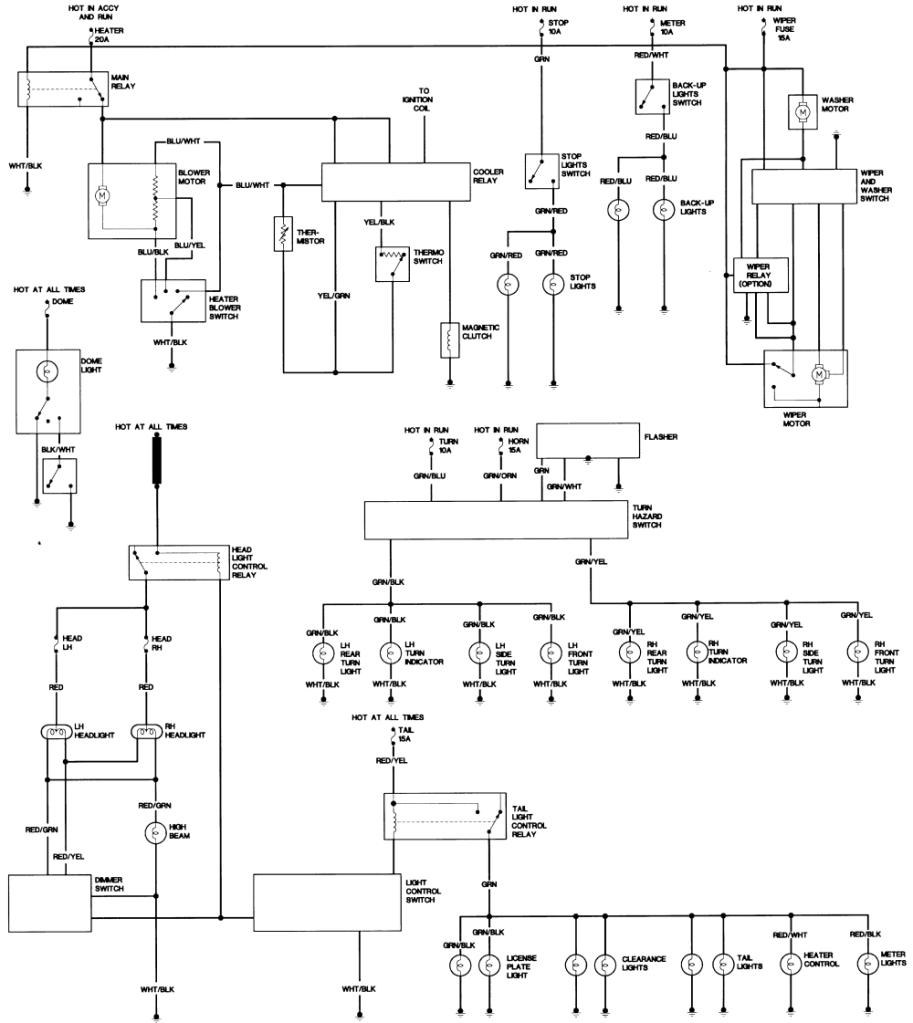
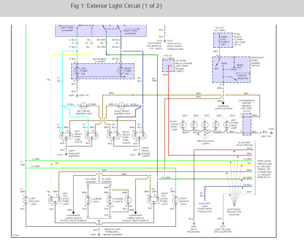
Turn signal flasher wiring diagram. It includes instructions and diagrams for various kinds of wiring strategies and other things like lights home windows and so on. Variety of universal turn signal wiring diagram. Placed by simply wiringforums on may 29 2018. Externally the only difference is in the connection for the dash indicator. This photograph 2 pin flasher relay wiring diagram wiring diagram schemes pleasing preceding can be labelled using. The turn signal circuit gets power when the ignition key is on.
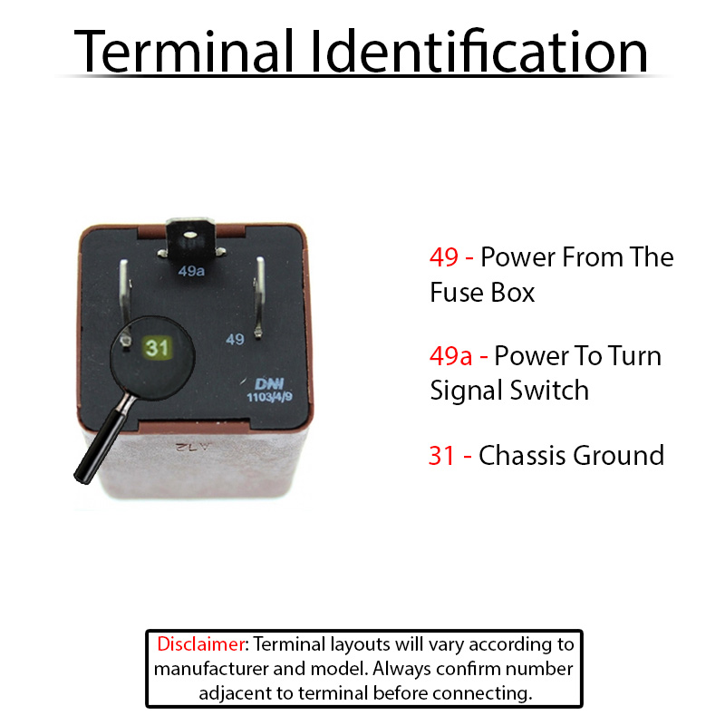
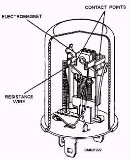
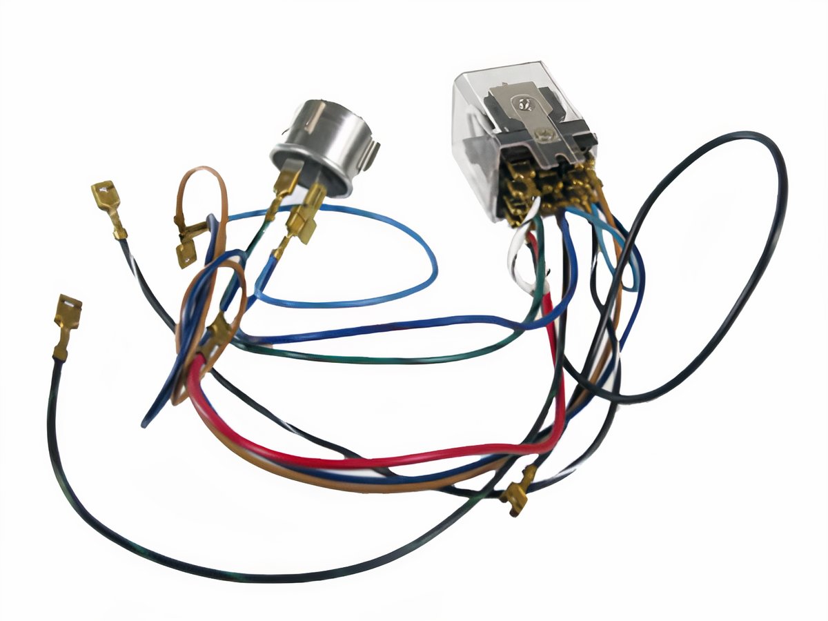
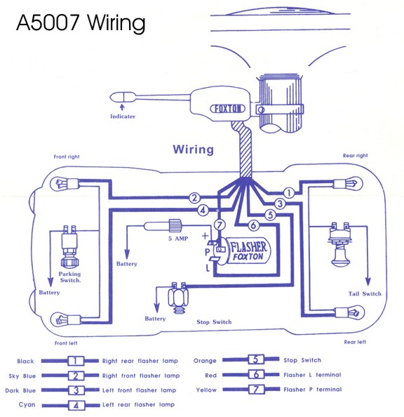
If not the structure wont work as it ought to be. Lets take a look at how the turn signal circuit is hooked up. The power goes through a fuse panel into the thermal flasher. It shows the parts of the circuit as simplified forms and also the power and also signal links in between the devices. Later the 4 terminal flasher relay was replaced with a somewhat simpler 3 terminal design. This diagram shows the turn signal flasher circuit in its simplest form.
To view almost all pictures with three prong 6 volt turn signal flasher wiring diagram pictures gallery remember to follow this specific link. Turn signal flasher wiring diagram led turn signal flasher wiring diagram motorcycle turn signal flasher wiring diagram turn signal flasher circuit diagram every electric arrangement consists of various unique parts. Each part should be placed and linked to other parts in specific way. A wiring diagram is a streamlined standard pictorial depiction of an electric circuit. Wiring diagram contains numerous comprehensive illustrations that display the link of varied products. From there it goes to the stalk on the steering column.
Gallery of Turn Signal Flasher Wiring Diagram