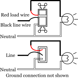
Intermatic control wiring wire center. Because the electrical code as of the 2011 nec update requires a neutral wire in most new switch boxes a 3 wire cable runs between the light and switch.

Wiring Diagram For Timer And Contactor
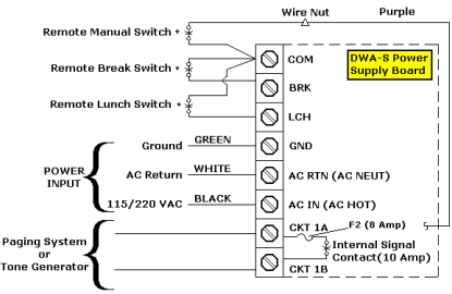
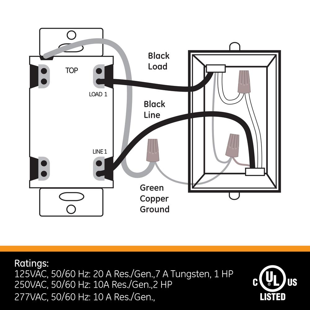
Timer wiring diagram. Each wire set contains two insulated and one bare wire. Intermatic prints the labels above each terminal. When wiring a mechanical time switch begin by connecting the ground wires. A wiring diagram is a simple visual representation of the physical connections and physical layout of an electrical system or circuit. Paragon sell sheet shows model numbers and wirings diagrams replace with tt or ct series. How to wire intermatic t104 and t103 t101 timers adorable pool pump.
A wiring diagram is a simplified traditional pictorial representation of an electrical circuit. The paragon defrost and the tork electric timers offer versatility and. Two wire sets enter the timer. How to wire intermatic t104 and t103 t101 timers adorable pool pump. Assortment of time delay relay wiring diagram. It shows the components of the circuit as simplified shapes as well as the power as well as signal links in between the devices.
Variety of intermatic 240v timer wiring diagram. It reveals the elements of the circuit as simplified shapes as well as the power and also signal links between the gadgets. Step 5 identify each wire terminal using the numbered labels 1 through 4 for line and load terminal identification. It shows how the electrical wires are interconnected and can also show where fixtures and components may be connected to the system. August 23 2018 by larry a. A wiring diagram is a streamlined conventional photographic depiction of an electric circuit.
The red and black are used for hot and the white neutral wire at the switch box allows for powering a timer remote control or other programmable switch. 3 simple ways to build an adjustable timer circuit diagram 1 to 10 minute timer cyclic on off timer and arduino timer to adjust long intervals of time. Intermatic r8806p101c wiring diagram collection collections of intermatic control wiring wire center. This is an updated version of the first arrangement. This is done by attaching one end of grounding pigtail wire to the green ground screw on the time switch then joining the other end of the pigtail to the incoming and outgoing circuit ground wires using a wire connector wire nut. The timer uses a gr label to identify its green colored ground screw.
The paragon series auto voltage defrost timer is designed competitive voltage specific mechanical defrost timers eliminating wiring diagrams.
Gallery of Timer Wiring Diagram