Telephone wiring diagram with the telephone wiring diagram below you will not only accomplish a project on your own you will keep that money in your pocket where it belongs. Phone companies would love you to think that you should not do your own wiring but i am here to dispel that myth.
Wiring Circuit Diagram Telephone Wiring
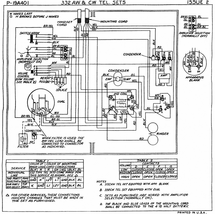
Telephone wiring diagram. The kind of wire shown above has recently become obsolete. Generally the information in the library is limited to equipment that was made prior to 1980. Search for the phone model and wiring or schematic eg. There will be a small box with a phone line going in and coming out. Most phone wire installed in the us. Telephone wiring for a phone outlet is typically either 1 2 or 3 pairs 2 4 or 6 conductor.
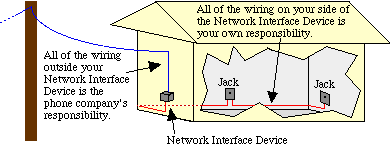
The phone line usually comes in by your electrical panel. This telephone wiring diagram shows the standard wiring for telephone jacks explaining the wiring connections for. You should disconnect the main phone line from the source before continuing wiring a phone jack. North 5h6 wiring this is a library of basic schematics wiring diagrams and other information that can be useful to anyone interested in restoring or repairing vintage telephone equipment. For all new telephone wiring projects you should use cat 5 cable. Wiring a jack is not difficult and it is totally fine to add a new jack or internet phone jack to your system.
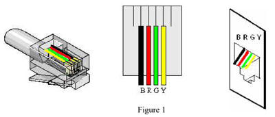
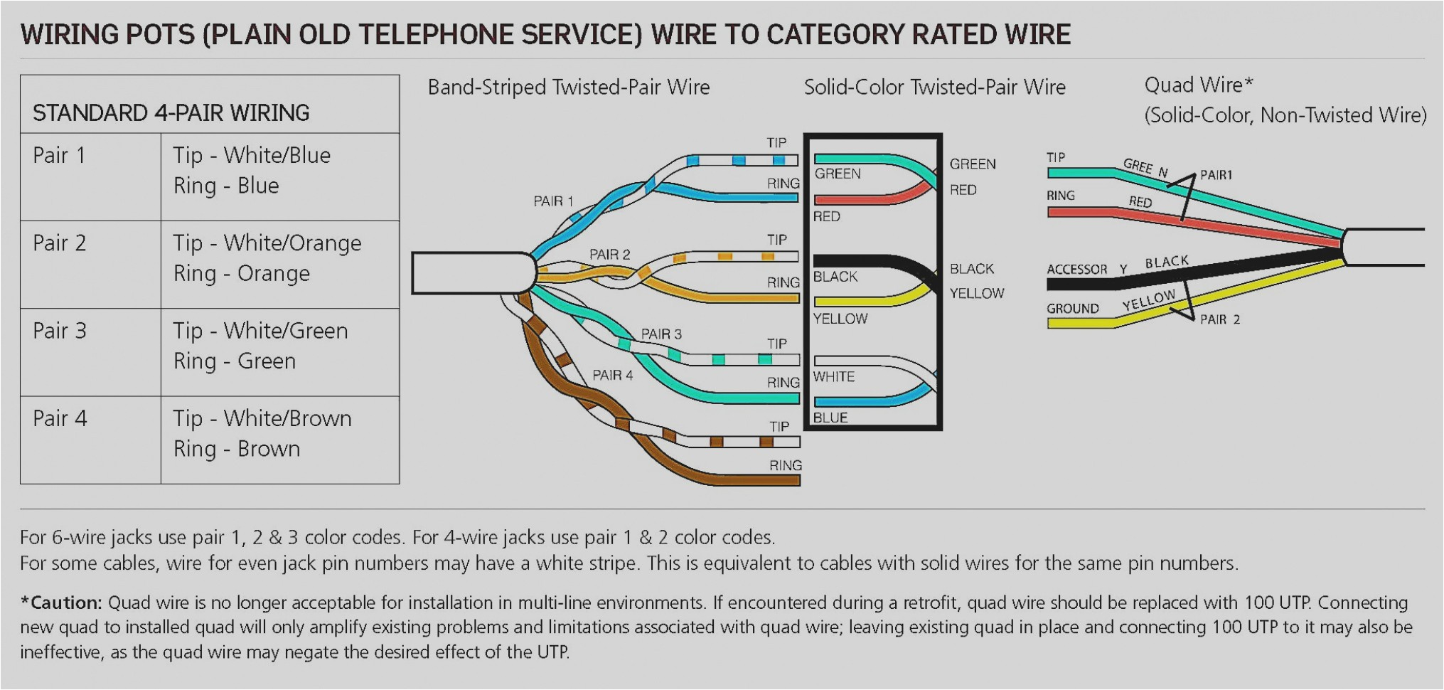
There may be instances where you may need to connect to or transpose from the old quad cable. The red telephone wire. Most cable nowadays is utp unshielded twisted pair. During the second half of the 20th century is of the following kind. Telephone wiring diagram for standard telephones. The diagram below provides the transposition between these standards.
In most residential phone wiring the cable contains four individual wires.
Gallery of Telephone Wiring Diagram