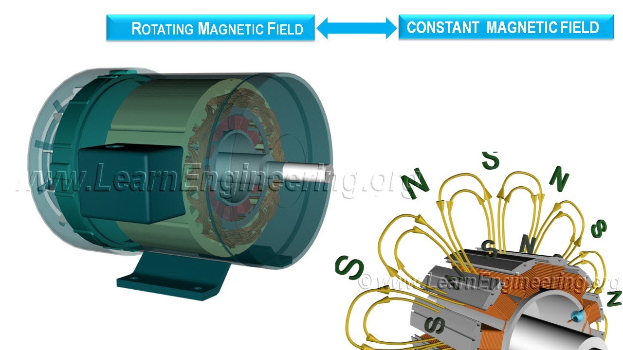
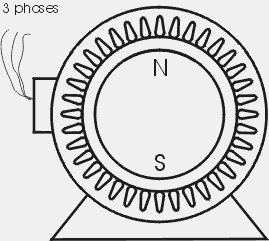
These motors contain multi phase ac electromagnets on the stator of the motor that create a magnetic field that rotates in time with the oscillations of the line current. Whatever you are we attempt to bring the web content that matches just what you are trying to find.
Ac Motors
Synchronous motor wiring diagram. Split phase ac induction motor operation with wiring diagram for size. The stator is the stationary part of the motor and rotor is their rotating part. A synchronous motor is doubly fed if it is supplied with independent excited multi phase ac electromagnets on both the rotor and stator. We attain this specific wonderful illustrations or photos from online and select one of the better intended for you. Or you are a trainee or maybe even you who simply wish to know concerning asynchronous motor wiring diagrams. 1 synchronous motor.
Terminal markings and internal wiring diagrams single phase and. 800 x 600 px source. It usually shows how to wire the motor for common configurations such as 110 to 125 volts or 220 to 250 volts and occasionally 208 volts. A synchronous motor rotates at a constant speed in proportion to the ac power. For example in type number ss25 the ss indicates standard slo syn which has a synchronous shaft speed of 72 rpm at 120 volts 60 hertz. The block diagram shows the drive electronics associated with a low voltage 12 v dc synchronous motor.
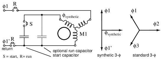
The stepping motor is transformed into a synchronous motor by replacing the wound wire for the ac power specification. In stator winding two effects are to be considered the effect of field cutting stator conductors at synchronous speed and the effect of stator. Ac synchronous motor in more detail. The wiring diagram is usually on the inside of the wiring boxs cover. These motors have a position sensor integrated within the motor which provides a low level signal with a frequency proportional to the speed of rotation of the motor. The stator is excited by the three phase supply and the rotor is excited by the dc supply.
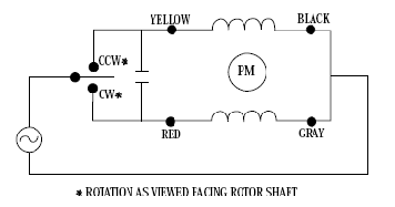
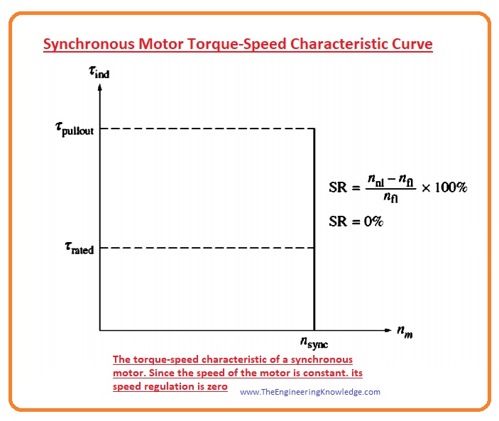
The alternating current windings of two phase alternating current generators and synchronous motors shall have terminal markings as given in mg 1 266 for two phase single speed induction motors. In case of a synchronous motor revolving field structure is to be energized by direct current dc current. 22 ac identification system the type number identification system for slo syn synchronous motors is straightforward and easily understood. A synchronous electric motor is an ac motor distinguished by a rotor spinning with coils passing magnets at the same rate as the alternating current and resulting magnetic field which drives it. Ac synchronous motor wiring diagram photos and photographs range this revealed below was accurately chosen plus authored by admin just after deciding on people who would be best one of many others. Working principle of a synchronous motor the stator and the rotor are the two main parts of the synchronous motor.
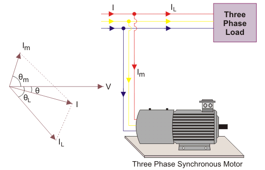
You could come from an. V terminal voltage r e effective resistance x l leakage reactance x a fictious reactance x s synchronous reactance e counter emf. By following the wiring diagram you can easily set the motor between voltages.
Gallery of Synchronous Motor Wiring Diagram