But today i can say that this type of engine is no longer such a difficult challenge as they are starting to get more a. On the other hand the diagram is a simplified variant of this structure.

Stepper Motor Wiring Diagram Electronics Stepper Motor
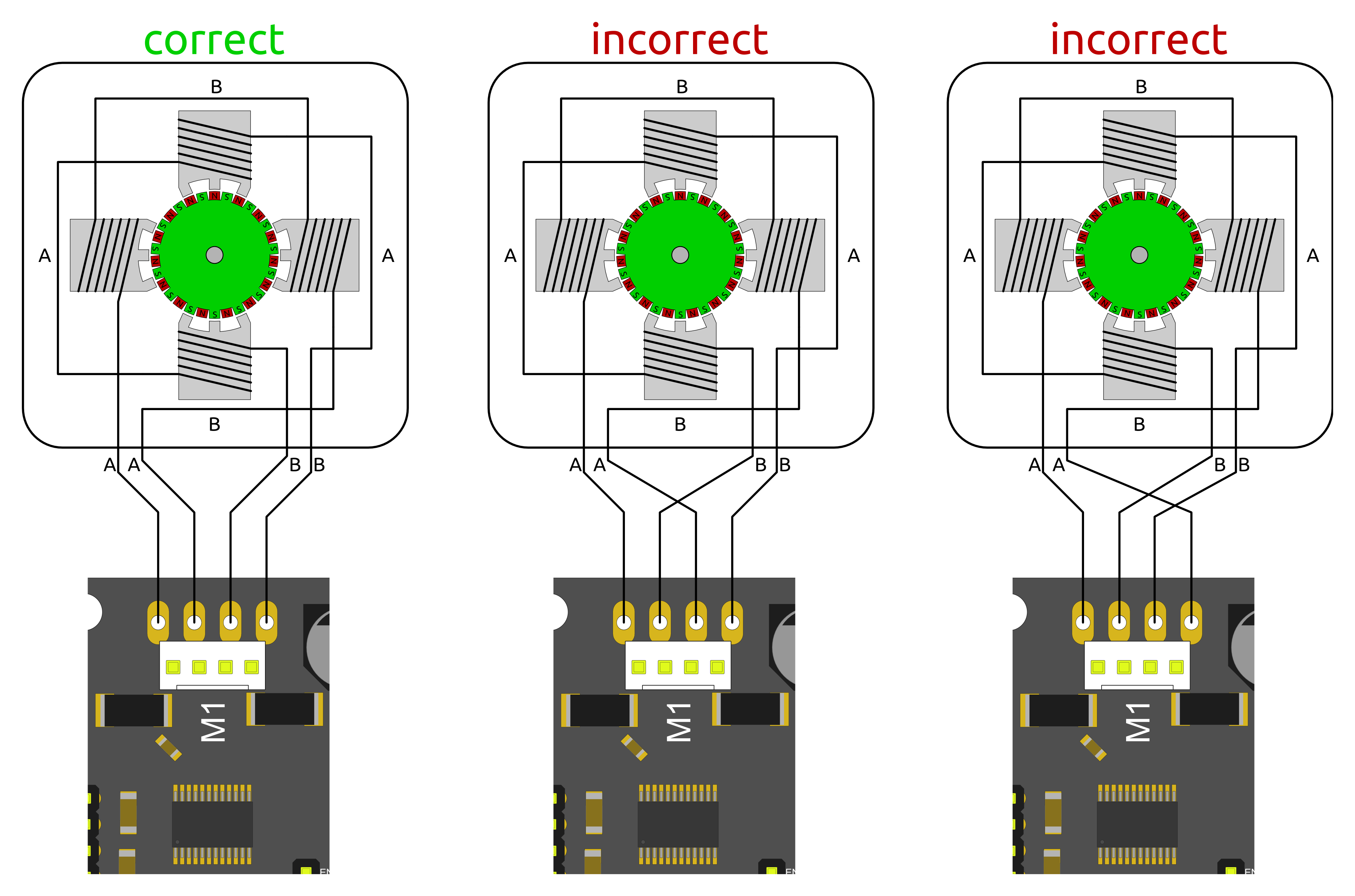
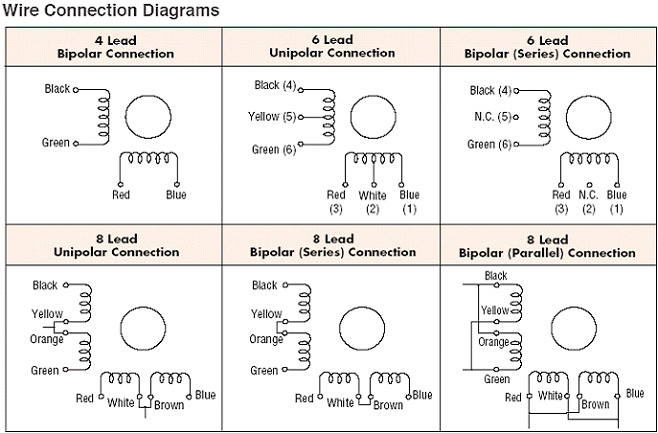
Stepper motor wiring diagram. Assortment of stepper motor wiring diagram. It shows the components of the circuit as simplified shapes and the facility and signal connections amid the devices. Please download these stepper motor wiring diagram by using the download button or right click on selected image then use save image menu. Collection of stepper motor wiring diagram youll be able to download free of charge. 4 wire stepper motor connection diagram wiring diagram is a simplified suitable pictorial representation of an electrical circuit. This allows the stepper to be connected as a unipolar motor as well as three different bipolar combinations.
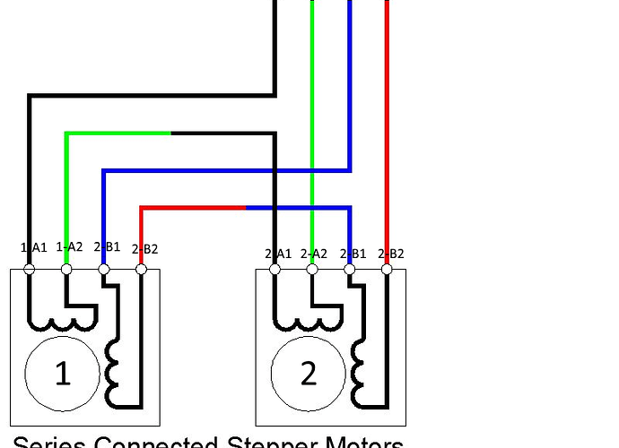
Bipolar stepper motors have two windings which are not connected to each other wired internally like this. In addition to the bipolar half and full winding modes you can also connect the two halves of each phase in. Wiring diagrams help technicians to find out how the controls are wired to the system. A wiring diagram is a simplified standard pictorial representation of an electrical circuit. Nema 17 step motor wiring diagram you should know oyostepperover stepper motor wiring diagram the diagram provides visual representation of a electrical structure. 4 5 6 and 8 wire stepper motors.
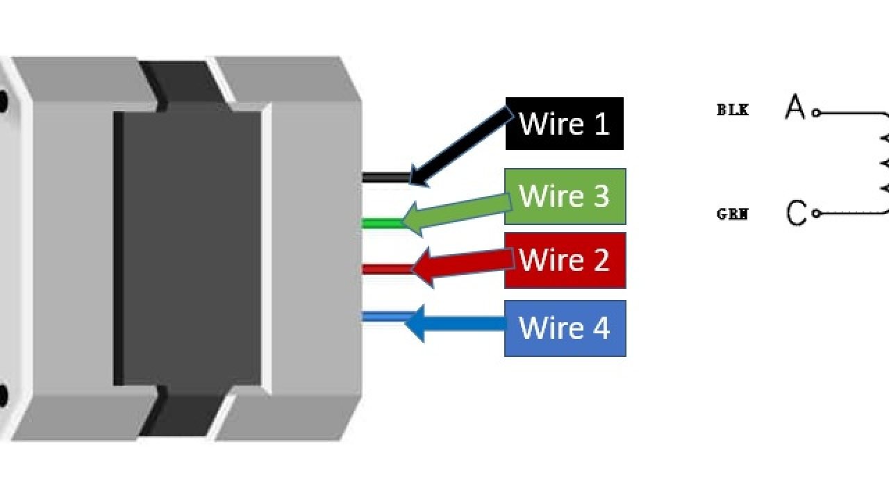
Nema 23 stepper motor wiring diagram wiring diagram is a simplified welcome pictorial representation of an electrical circuitit shows the components of the circuit as simplified shapes and the aptitude and signal friends amongst the devices. This is a common word during discussions involving peculiarities of step motors which can have 4 5 6 and 8 wires. If your stepper motor has 4 wires it is a bipolar stepper motor. It makes the procedure for assembling circuit easier. An eight wire motor is similar to a six wire motor except that each of the two phases is split into two separate windings. Since coils a and b on the diagram above are not connected the resistance between leads a1 and b1 or between a1 and b2 will be infinite.
It shows the components of the circuit as simplified forms as well as the power and also signal links in between the tools.
Gallery of Stepper Motor Wiring Diagram