Stc 3018 cf digital temperature controller. Dec 10 diy stc 2 stage temperature controller wiring diagram with indicator lights time to go autonomous.

웃 유w3230 Ac 110v 220v Dc12v 24v Digital Thermostat
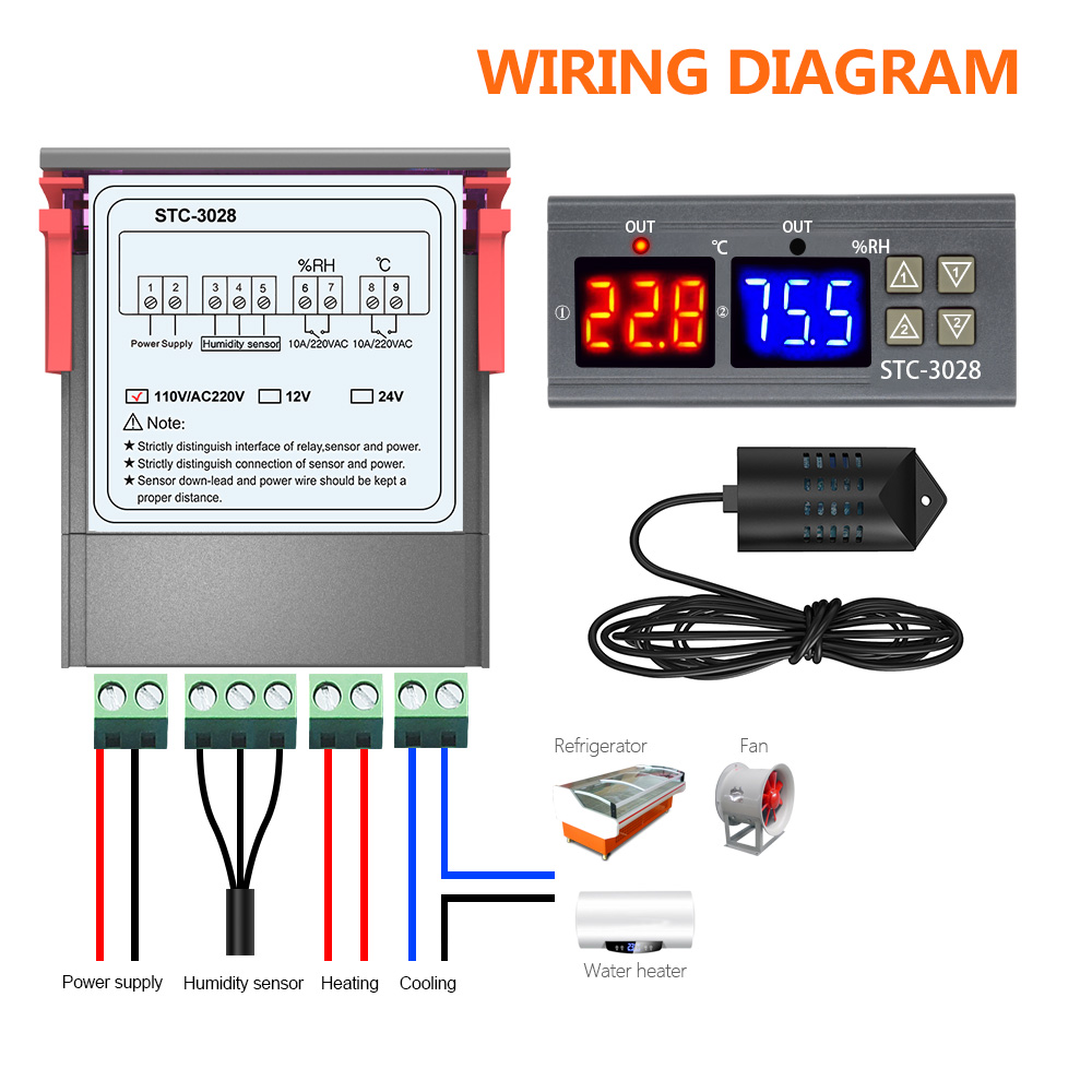
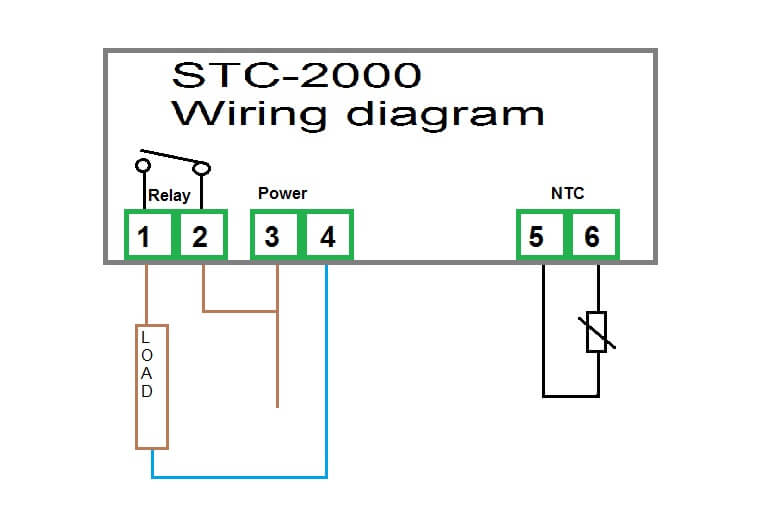
Stc 3018 wiring diagram. The diagram shows a volt alternating current supply vac which is how to wire up a socket with the stc temperature controller. Schematic for cooler heater with stc 1000 thermostat. Stc 3018 12v 24v 220v digital temperature controller cf thermostat relay 10a heatingcooling thermoregulator with dual led display cod. Wiring harnesses that were supplied with the switches have three wires two of which we are using. Package price 1 items. 160mm 70mm 300mm 48mm 330mm.
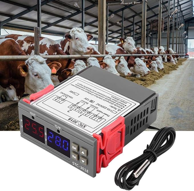
How a load in a thermostat we can plug heater spiral motor heater bulb similar is on picture. Stc 3018 12v 24v. Milling cutter installation copper chuck. 55 c 120 c 66f248f. Dont worry about the manufacturer an stc is an stc regardless of who made it. The green wire is the common of the switch and the black is the normally open contact.
A right diagram of the thermostat stc1000. Tig en tighten tig en. M5x10 tv15 42mm 28mm e e oo e e 58mm zaxis spindle xaxis yaxis. This video is part 1. Setting parameters on the mypin t series pid controller duration. Add to cart save.
Screw the m3 set screws into the copper chuck. Code wire colour code wire colour b black p pink br brown r red g green sb sky blue gr gray si silver l blue v violet lg light green w white o orange y yellow if a cable has two colours the first of the two colour code. Various connecting wire must be well connected with the terminal otherwise it would result in reducing the reliability of machine. How to read the wiring diagrams wire colour codes a 9 wire colour codes wire colours are identified by the follow colour codes. Install the copper chuck into the motor and tighten the screws. Wiring diagrams step motor x y z laser 12v 5amax spindle 12 36v 12 36vdc 24v power adapter connect your cnc to computer using the bundled usb cable.
How to wire the stc 1000 temperature controller duration. Therefore each limit switch black 3 pin connector plugs into the header with the green wire to the upper pin and the black wire to the lower pin.
Gallery of Stc 3018 Wiring Diagram