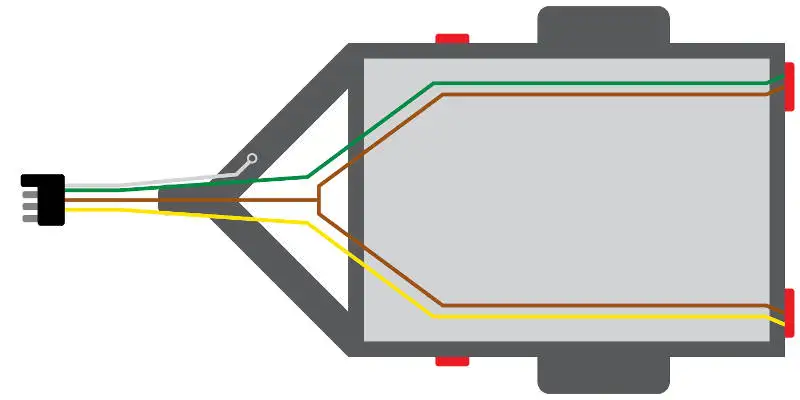
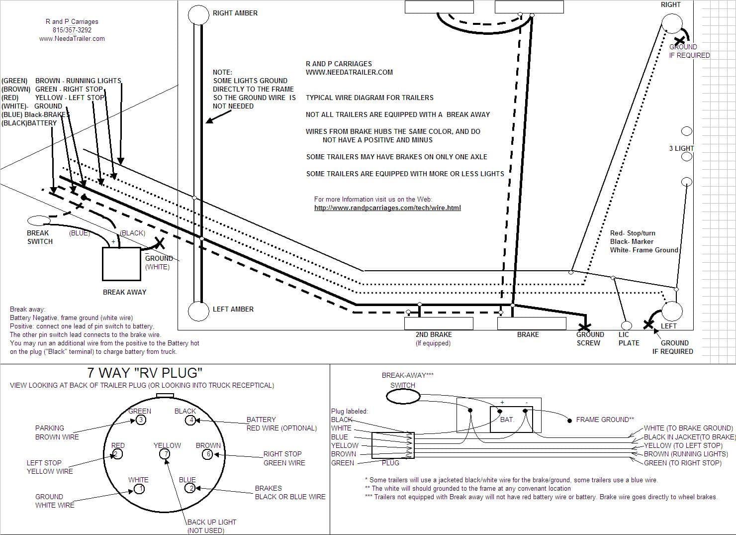
Extrapolate the same expansion for additional axles. Below is the generic schematic of how the wiring goes.

Trailer Wiring Connector Diagrams Conductor Plugs Trailer
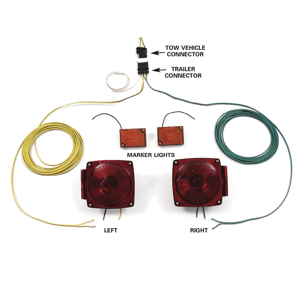
Small trailer wiring diagram. A wiring diagram is a streamlined traditional photographic depiction of an electric circuit. This project requires a trailer lighting kit that includes a wiring harness small connection clips a couple rear turn signals and a couple side mounted lights. Only the blue brake and white ground wires are different. Collection of travel trailer wiring schematic. 5x10 trailer packem trimmer racks equipment defender blower rack. Complete with a color coded trailer wiring diagram for each plug type this guide walks through various trailer wiring installation solution including custom wiring splice in wiring and replacement wiring.
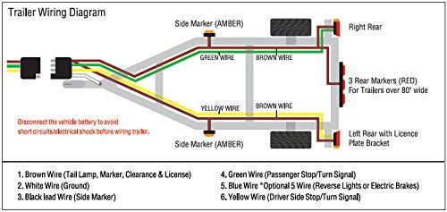
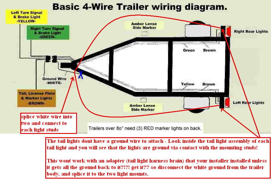
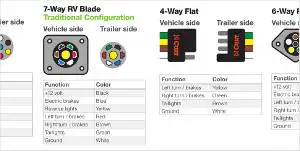
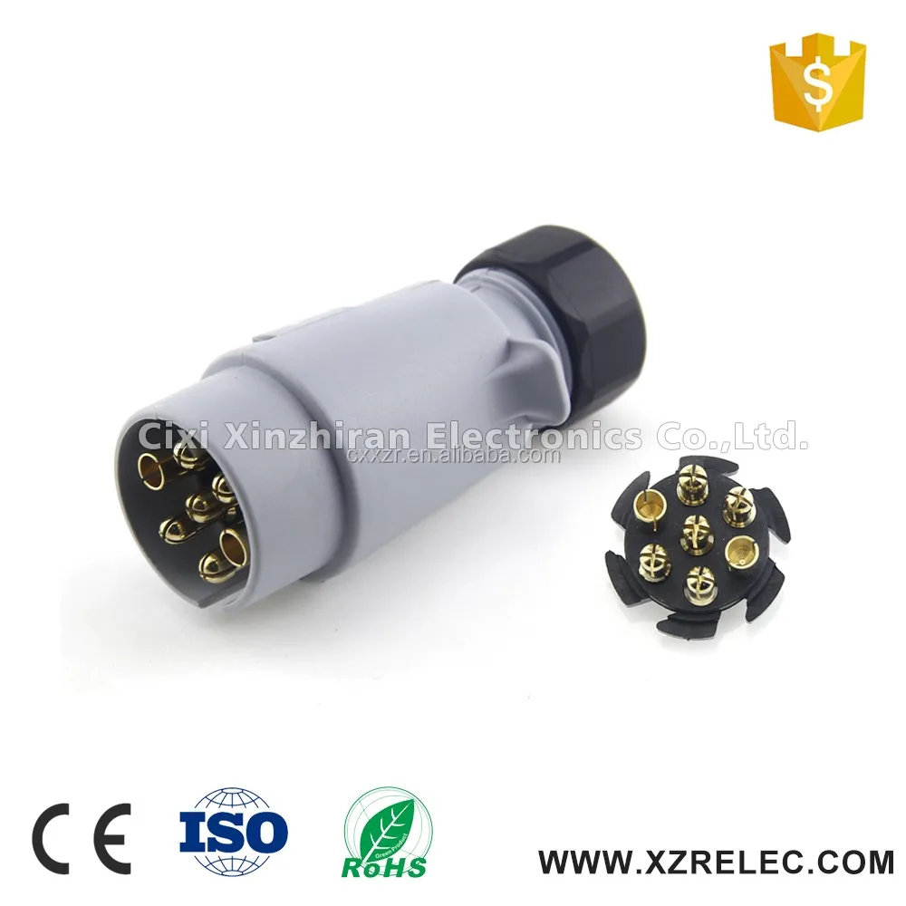
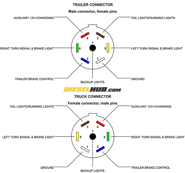
Various connectors are available from four to seven pins that allow for the transfer of power for the lighting as well as auxiliary functions such as an electric trailer brake controller backup lights or a 12v power supply for a winch or interior trailer lights. Trailer wiring diagrams trailer wiring connectors various connectors are available from four to seven pins that allow for the transfer of power for the lighting as well as auxiliary functions such as an electric trailer brake controller backup lights or a 12v power supply for a winch or interior. Can also be used as custom wiring on trailers with 3 lightwire systems. As the name implies they use four wires to carry out the vital lighting functions. 4 way trailer connectors are. The four wires control the turn signals brake lights and taillights or running lights.
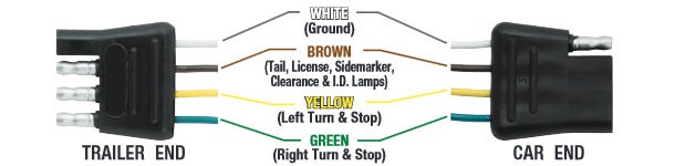
Typical trailer wiring diagram and schematic. Trailer wiring diagrams trailer wiring connectors. 34 inch by 1 inch 6 way rectangle connectors right turn signal green left turn signal yellow taillight brown ground white. 4 way trailer connectors are typically used on small trailers such as boat snowmobile utility and other trailers that that do not use brakes. If your vehicle is not equipped with a working trailer wiring harness there are a number of different solutions to provide the perfect fit for your specific vehicle. The red and blue wire can be used for brake control or auxiliary.
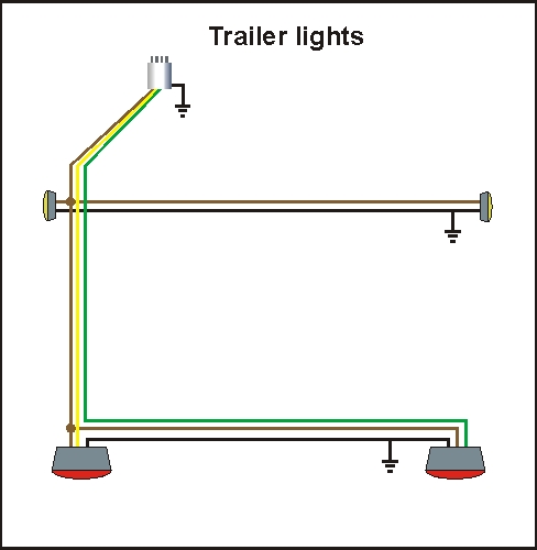
These 2 wire diagrams fit the needs for most trailers. The image above shows a single axle trailer and the next image shows wiring for tandem axles. Above we have describes the main types of trailer wiring diagrams. Utility trailer 03 4 pin trailer wiring and diagram duration. Use on a small motorcycle trailer snowmobile trailer or utility trailer. Trailer light wiring basics it will help to have an understanding of trailer light systems and we recommend reviewing trailer wiring diagrams before starting this project.
They also provide a wire for a ground connection. 4 pin trailer wiring diagram. It reveals the parts of the circuit as streamlined shapes as well as the power and also signal links in between the gadgets. To connect the electric system of your trailer to the vehicle you will be using special connector.
Gallery of Small Trailer Wiring Diagram


/trailer-wire-colors-589d62645f9b58819cf8721f.gif)

