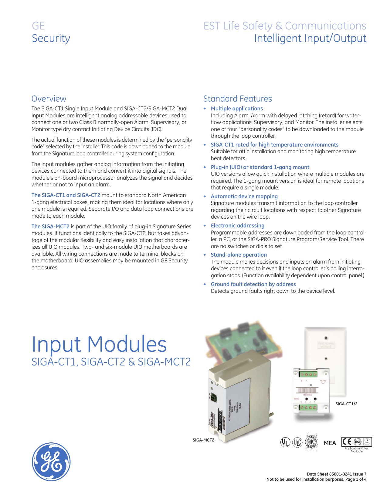
It functions identically to the siga ct2 but takes advan. Siga ct2 dual input module siga dg detector guard siga dgs surface adapter for use with the siga dg detector guard.
Signature Amp V Series Detectors And Modules Ppt Video
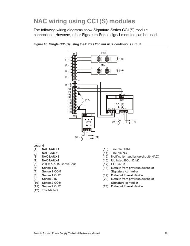
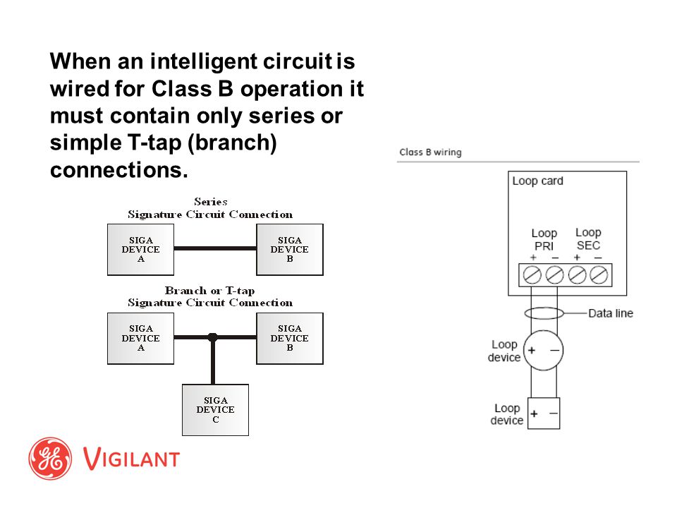
Siga ct2 wiring diagram. Verify that all field wiring is free of opens shorts and ground faults. The siga mct2 is part of the uio family of plug in signature series modules. Make all wiring connections as shown in the diagram. Plug the siga mct2 into any available position on the motherboard and secure the module to the motherboard with the captive screws. 5 write the address assigned to the pull station on the label provided and apply the label to the pull station. Signs that represent the parts in the circuit as well as lines that represent the links between them.
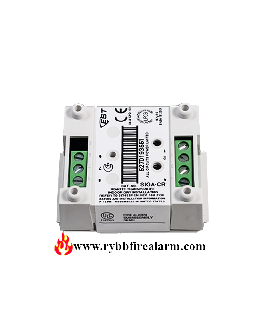
A wiring diagram is a streamlined traditional photographic representation of an electric circuit. Before replacing a siga cc1 module tag the wires to ensure correct reconnection. Separate io and data loop connections are made to each module. This type of diagram is like going for a photograph in the parts and wires all connected up. The edwards est siga ct2 dual input module is an intelligent analog addressable device used to connect one or two class b normally open alarm supervisory or monitor type dry contact initiating device circuits idc. About 6 mm from the ends of all wires that.
For use exclusively with edwards ests signature loop controller. Siga cr wiring diagram a wiring diagram is a simplified traditional photographic representation of an electric circuit. Wiring connections are made to the terminals on the motherboard see wiring diagram. Siga ct2 wiring diagram. The siga ct1 and siga ct2 mount to standard north american 1 gang electrical boxes making them ideal for locations where only one module is required. It shows the elements of the circuit as simplified forms and also the power and also signal links between the toolscr wiring diagram detailed wiring diagramssiga ct1 wiring diagram best.
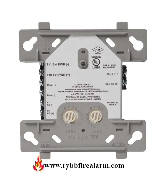
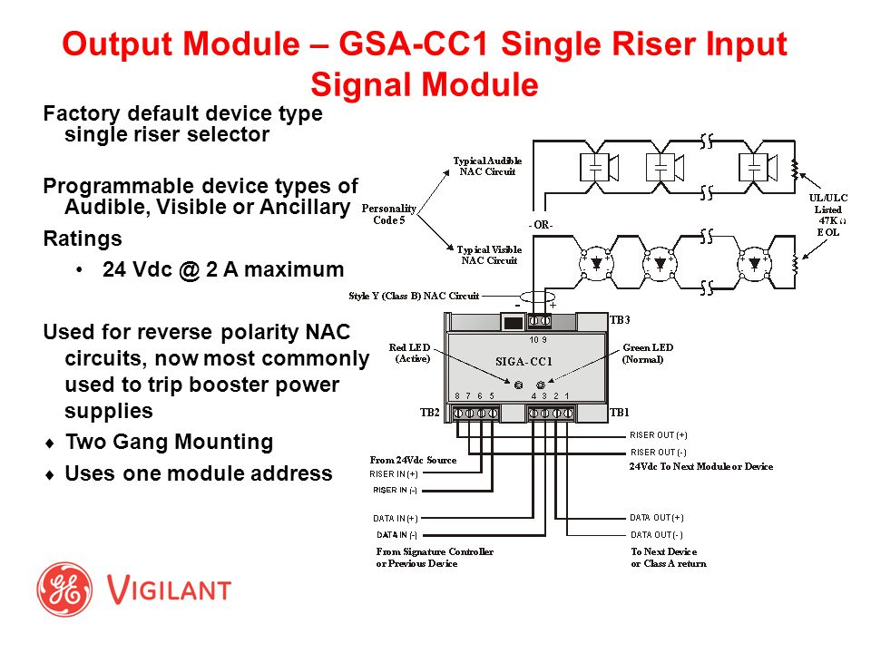
It shows the elements of the circuit as simplified shapes and also the power as well as signal links between the devices. To wire the module. The siga cc1 module does not supervise the riser. Mount the uio motherboard inside a suitable est enclosure with screws and washers provided. Wiring diagram images detail. A wiring diagram is a type of schematic which utilizes abstract photographic signs to show all the affiliations of parts in a system.
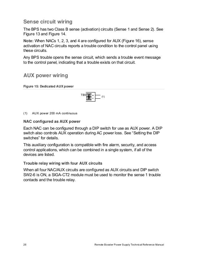
Wiring layouts are made up of 2 points. The relay contains a red led which indicates the relay coil is ener gized. Siga ct2 wiring diagram whats wiring diagram. Siga ct2 wiring diagram siga ct1 wiring diagram fresh siga sb wiring diagram siga rb eolican. Ac v ac or v ac by wiring to appropriate input terminals. Variety of siga ct2 wiring diagram.
The fire alarm control panel provides this function. Siga ct2 wiring diagram.
Gallery of Siga Ct2 Wiring Diagram