T l n l y1 y2. Low voltage switchgear and other power distribution equipment.
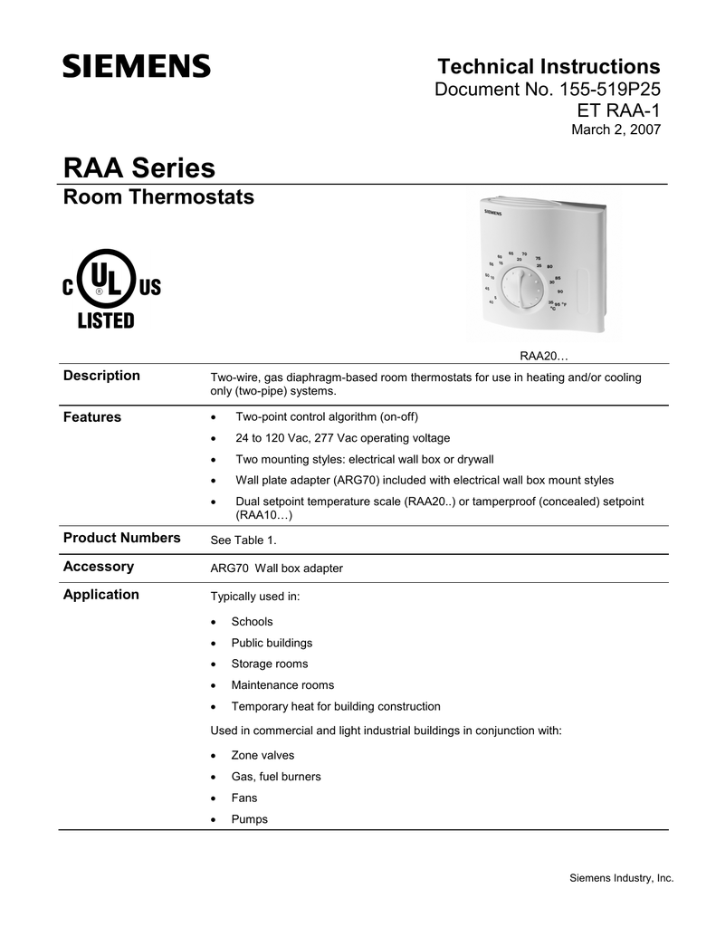
Raa20u Siemens Raa20u Raa Series Heat Cool Only
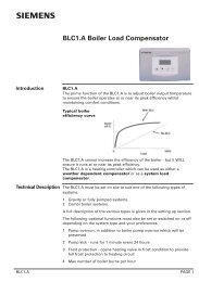
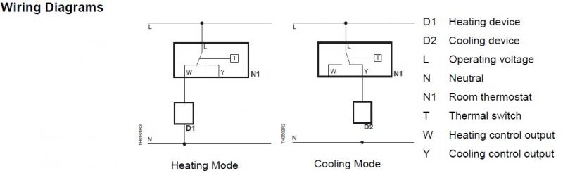
Siemens raa20 wiring diagram. Siemens building technologies room thermostat raa20 ce1n3002e hvac products 05092003 connection diagrams n l d1 y1 y2 n1 l t 3001a01 n l y1 y2 n1 l d2 t 3001a02 d1 zone valve or thermal valve for heating d2 zone valve or thermal valve for cooling l switching voltage ac 24250 v n1 room thermostat y1 control output heat ing ac 24250 v. Position thermostat housing over the two mounting lugs located at the top of the. D1 zone valve or thermal valve for heating. Wiring diagrams for typical tiastar units tool. 10 a t l n l y1 y2. Siemens motor control center wiring diagrams are at your fingertips within seconds.
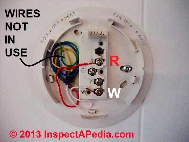
3 0 0 1 a 0 1. Use the tool below to quickly find and download one line diagrams. Thermostat is not position sensitive. Please find attached wiring diagram and suggest any correction in itthanks. 3 0 0 1 a 0 2. Pull the wiring through the thermostat housing.
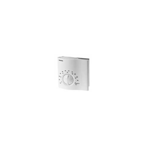
Level the mounting plate. Deari need to verify the wiring of 6es7321 1bl00 0aa06es7322 1hh01 0aa06es7331 7kf02 0ab0i have prepared wiring diagrams for these above modules. Two position control gas filled diaphragm adjustments the required temperature is selected by a setpoint adjuster on the front of the thermo stat. Siemens room thermostat raa20 ce1n3002en building technologies 2015 02 06. Using the two wood screws provided fasten sub base to wall. Page 2 arg701 adapter plate for surface wiring 112x130 mm arg702 technical design key features of the raa20 room thermostat.
Pull the wiring through the opening in the upper portion of the sub base.
Gallery of Siemens Raa20 Wiring Diagram