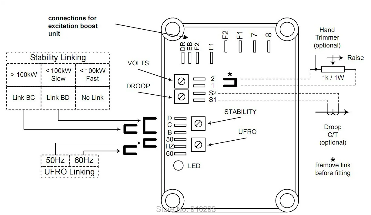
Clockwise increases the amount of ct. Excitation power is derived from a three phase permanent magnet generator pmg to isolate the avr control circuits from the effects of non linear loads and to reduce radio frequency interference on the generator terminals.
Da8 Mx321 Voltage Regulator Wiring Diagram Wiring Resources
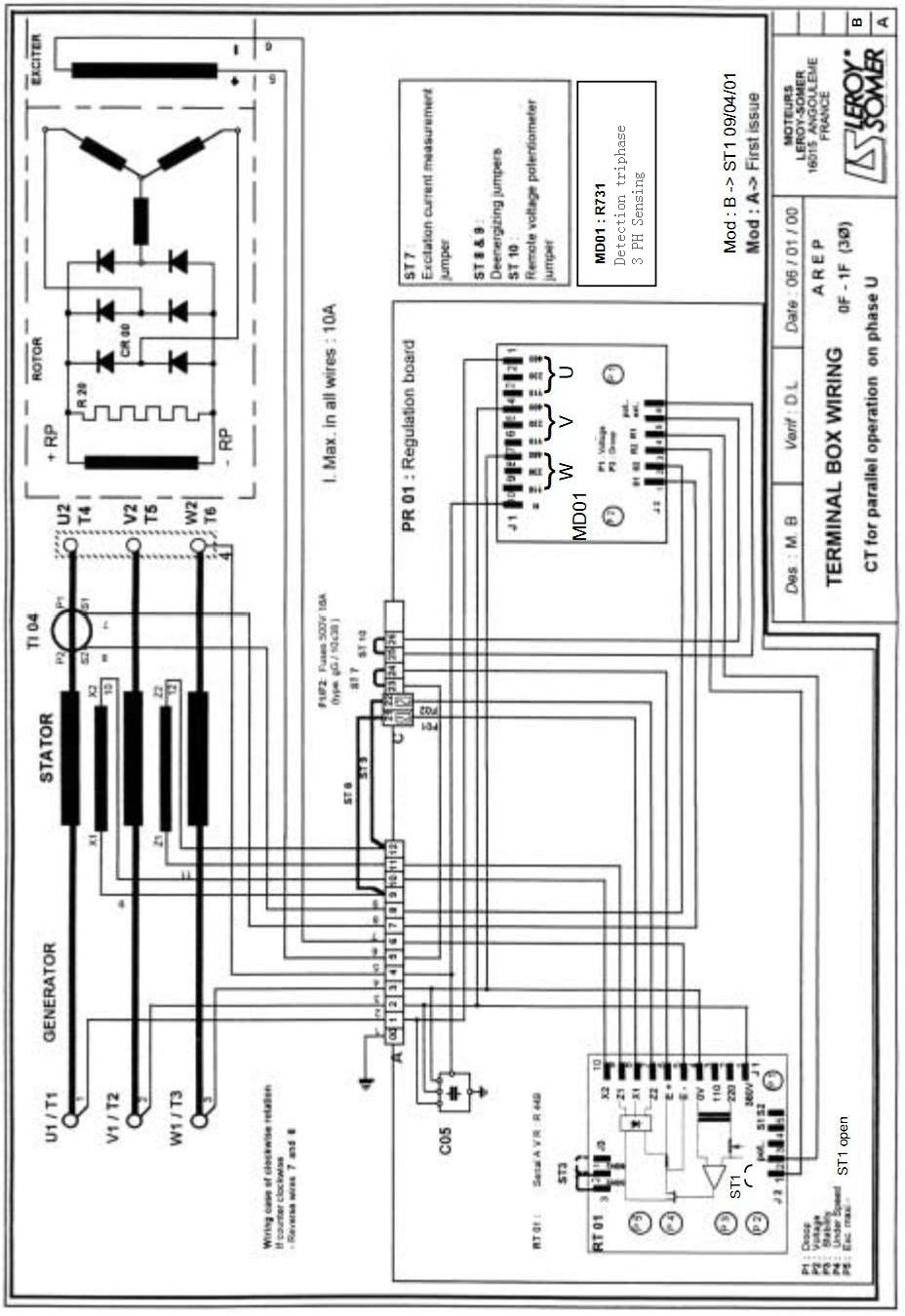
Mx321 2 avr wiring diagram. The droop adjustment is normally preset in the works to give 5 voltage droop at full load zero power factor. Refer to diagram in the back of this manual to determine wiring. All stamford generators are supplied with a declaration of incorporation for the. Is connected to s1 s2 on the avr see generator wiring diagram for details. Refer to wiring diagram before removing the shorting link and connecting the droop transformer. Control function turn potentiometer.
Fitting and operating refer to generator wiring diagram for connection details. Vac to vac maximum 3 phase 3 wire refer to alternator wiring diagram for connection details. Mx321 automatic voltage regulator avr specification controls and accessories. Mx automatic voltage regulator avr specification controls and accessories voltage. Control function turn potentiometer clockwise to. Mx automatic voltage regulator avr.
A043y701 issue 2 5 ref. Mx321 avr controls 6 a043y701 issue 2 32 initial avr setup notice the avr must be setup only by authorised trained service engineers. Signal injected into the avr and increases the droop with lagging power factor cos 0. Ay issue 2 5 ref. Refer to alternator wiring diagram for connection details. Is available as an option using either the mx or mx avr.
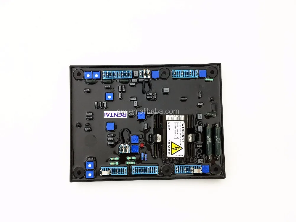
The droop transformer must be connected in the correct main output terminal for proper operation details are as shown in the machine wiring diagram. Mx321 is a three phase sensed automatic voltage regulator and forms part of the excitation system for a brush less generator. Mx321 automatic voltage regulator avr for cummins 1250kva generators.
Gallery of Mx321 2 Avr Wiring Diagram